EQ1092F型长头载货汽车制动系统的设计(含CAD图,CATIA三维图)(英文版)
1.无需注册登录,支付后按照提示操作即可获取该资料.
2.资料以网页介绍的为准,下载后不会有水印.资料仅供学习参考之用.
密 惠 保
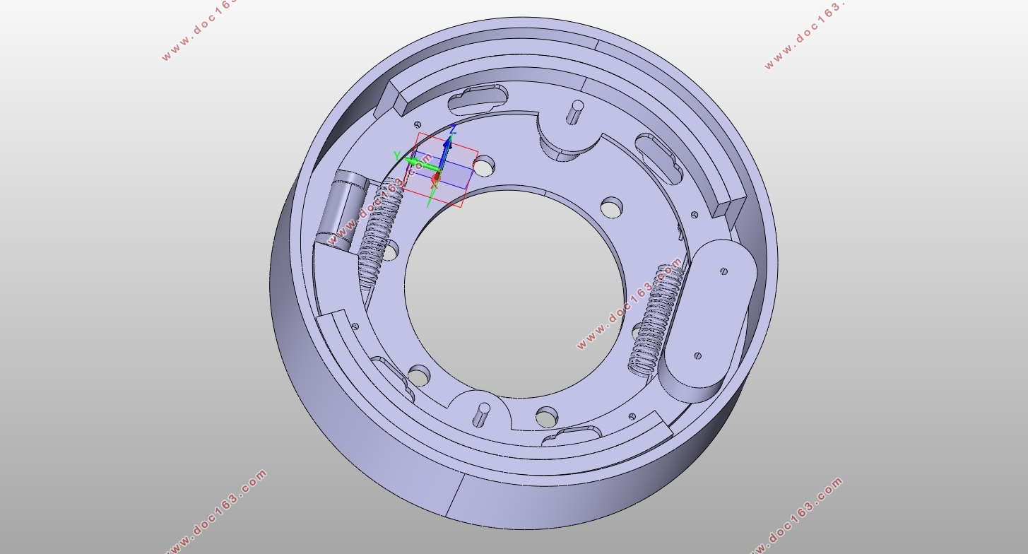
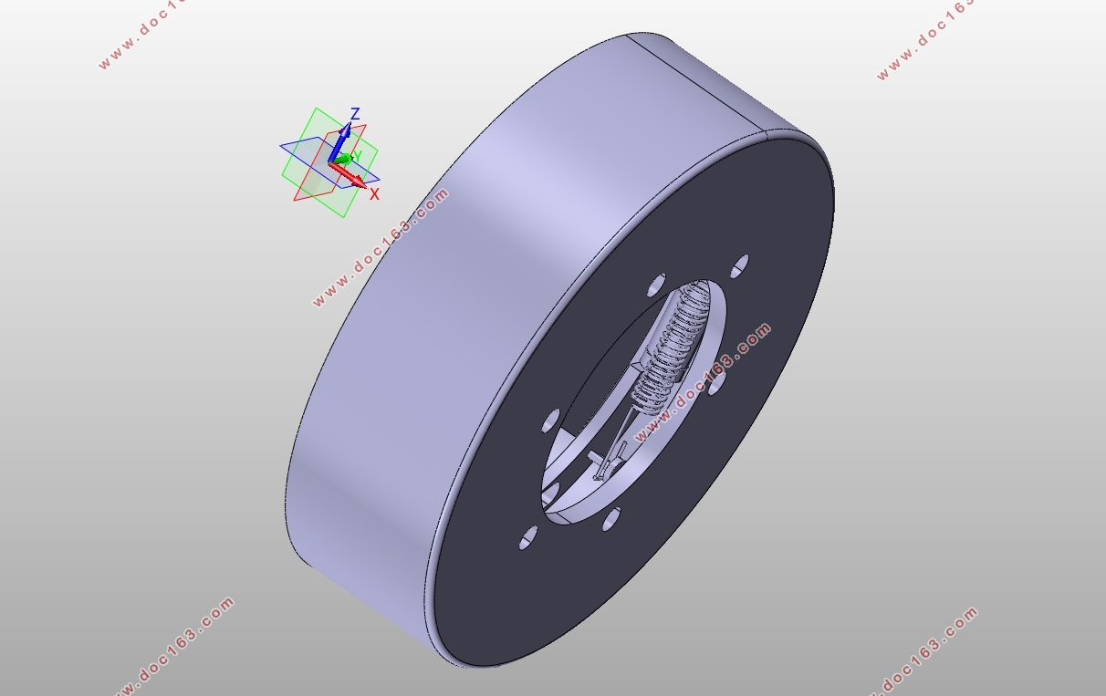
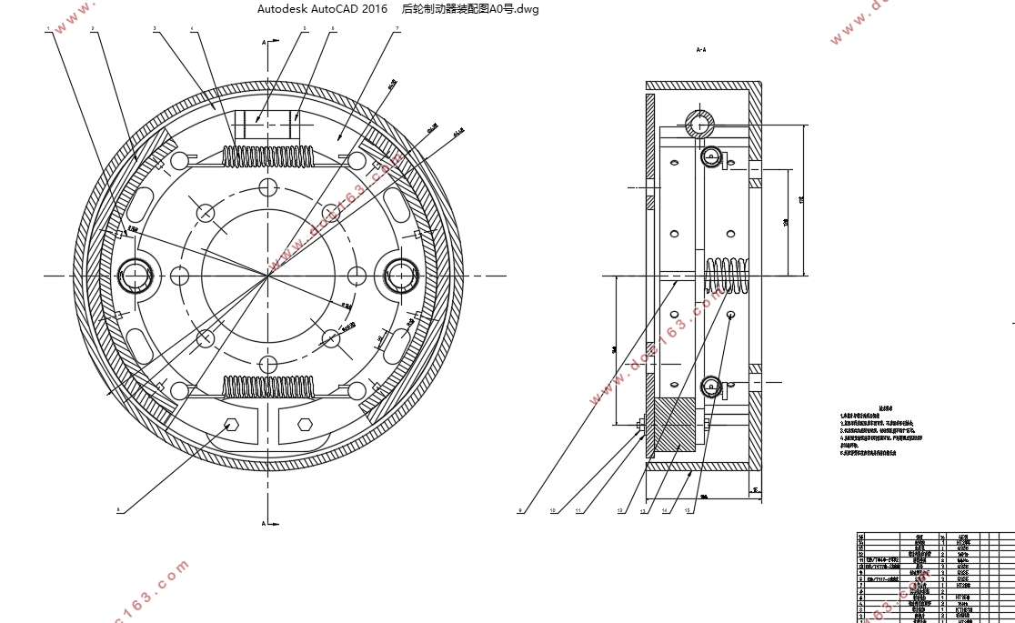
EQ1092F型长头载货汽车制动系统的设计(含CAD图,CATIA三维图)(英文版)(任务书,开题报告,外文翻译,文献摘要,论文说明书英文版2000字,CAD图7张,CATIA三维图)
摘要
汽车制动系是用以强制行驶中的汽车减速或停车、使下坡行驶的汽车车速保持稳定以及使已停驶的汽车在原地(包括在斜坡上)驻留不动的机构。随着高速公路的迅速发展和车速的提高以及车流密度的日益增大,为了保证行车安全,汽车制动系的工作可靠性显得日益重要。也只有制动性能良好、制动系工作可靠的汽车,才能充分发挥其动力性能。本文通过某载货汽车制动系统的设计,系统详细的将油压整车制动系统进行了阐述。制动系统匹配设计主要是根据设计任务书的要求,整车配置、布置及参数,参考同类车型参数,选择制动器型式、结构及参数,然后校核计算,验证所选参数是否满足设计任务书及法规要求,满足要求后初步确定参数。由于本文参考样车为油压制动车型,操纵系统为液压操纵、真空助力。
关键词:制动系统,制动力分配,同步附着系数,制动器
Abstract
The automobile brake system is a mechanism for forcibly decelerating or stopping a vehicle while driving, maintaining a stable vehicle speed on a downhill road, and mobilizing a parked vehicle in place (including on a slope). With the rapid development of the expressway and the increase of the vehicle speed and the increasing traffic density, the operational reliability of the automobile brake system becomes increasingly important in order to ensure the safety of the vehicle. Only cars with good braking performance and reliable braking system can fully exert their power performance. This article through the design of a truck brake system, the system detailed description of the hydraulic vehicle brake system. The matching design of the braking system is mainly based on the requirements of the design task book, vehicle configuration, layout and parameters. With reference to similar vehicle model parameters, the brake type, structure and parameters are selected, and then the calibration calculation is performed to verify whether the selected parameters meet the design mission statement and Regulatory requirements preliminarily determine the parameters after meeting the requirements. Because this article refers to the sample vehicle is a hydraulic brake model, the control system is hydraulically operated and vacuum assisted.
[资料来源:http://THINK58.com]
Key words:Braking system, braking force distribution, synchronous adhesion coefficient, brake
[版权所有:http://think58.com]

[来源:http://think58.com]
table of Contents
1.Introduction........................................................................................1
1.1 Purpose and significance......................................................1
1.2 Analysis of Research Status at Home and Abroad................1
1.3 Design content, goals, programs and measures...................2
1.3.1The basic content of the design.....................................2
1.3.2 Design goals...................................................................2
1.3.3Proposed technical solutions and measures..................2
1.3.4The brake system requirements.....................................3
2.Braking system main parameter selection..........................................7
2.1Initial selection of system main parameters...........................7
2.1.1The ideal braking force distribution curve is drawn.......7
2.1.2 Selection of Synchronous Adhesion Coefficient and Braking Force Distribution Coefficient.........................................................................10 [资料来源:http://think58.com]
2.2 Calculation and Selection of Main Parameters of Brake.........11
2.2.1 Front and rear axle braking force determination.........12
2.2.2 Determination of brake type........................................12
2.2.3 Determination of the braking radius............................12
2.2.4 Calculation and Selection of Brake Efficiency Factor....13
2.2.5Wheel cylinder diameter determination.......................14
2.2.6Brake drum inner diameter D........................................14
2.2.7Brake drum inner diameter D.........................................15
2.2.8Friction liner start angle..................................................15
2.2.9Distance from the center of the brake to the line of action of the opening force P........................................................................................16
2.2.10Brake shoe position coordinates k and c.......................16
2.3Determination of brake operating system parameters...............16
[资料来源:http://think58.com]
2.3.1 Initial calculation of system working pressure................16
2.3.2Master cylinder diameter, vacuum booster boost ratio, pedal lever ratio..........................................................................................................16
2.3.3 Vacuum booster diameter determination.......................17
3.Driving brake operating system calibration calculation.........................19
3.1 Pedal force calculation check......................................................19
3.2 Calculation of braking distance...................................................19
4.Full text summary...................................................................................21
5.References..............................................................................................22
[来源:http://think58.com]
上一篇:爱丽舍7163型轿车制动系统设计(含CAD零件图装配图)
下一篇:乘用车液压制动特性的基础研究(含CAD图,CATIA三维图)
