五菱荣光驱动桥的设计(含CAD零件图装配图)

1.无需注册登录,支付后按照提示操作即可获取该资料.
2.资料以网页介绍的为准,下载后不会有水印.资料仅供学习参考之用.
密 惠 保
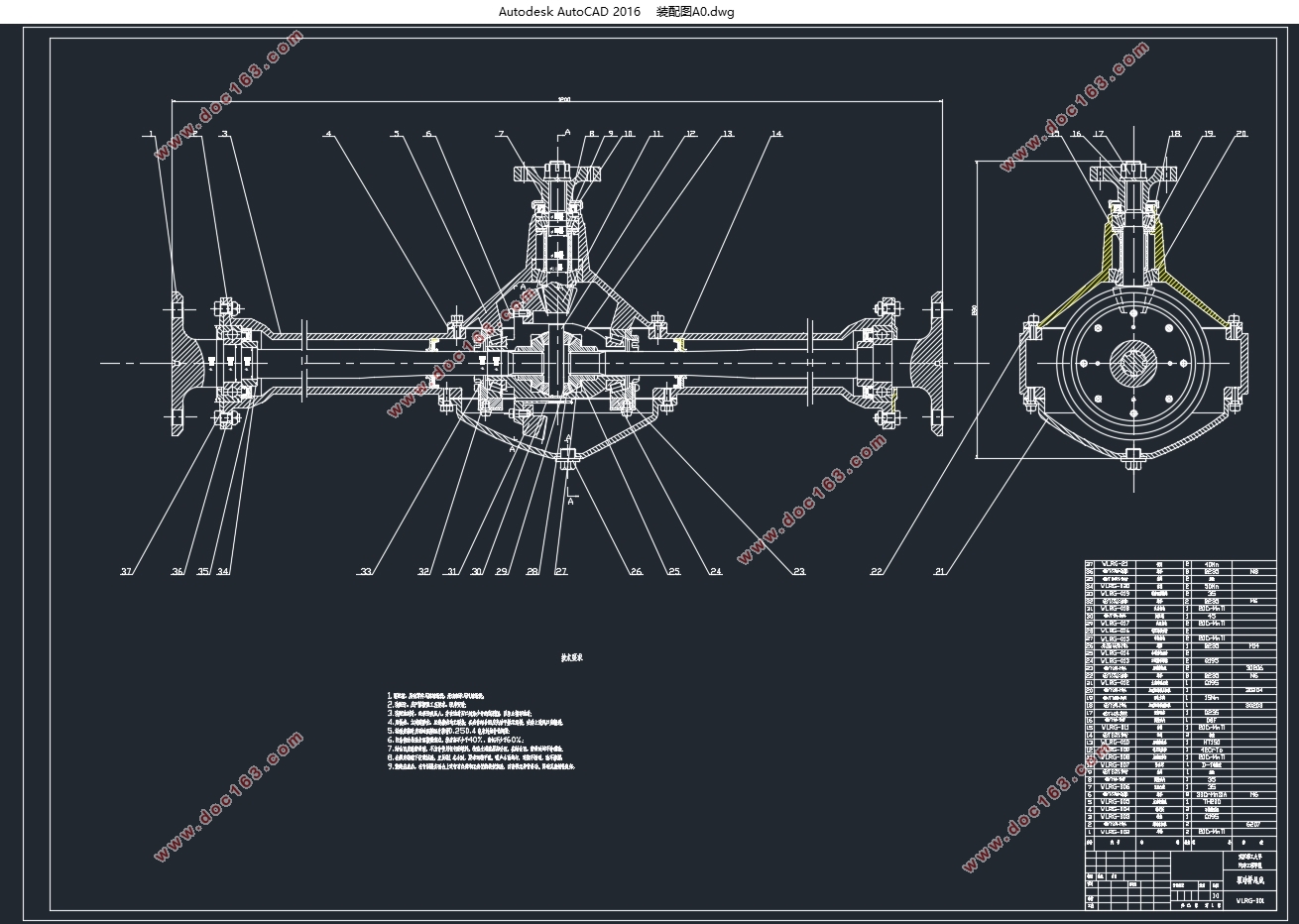
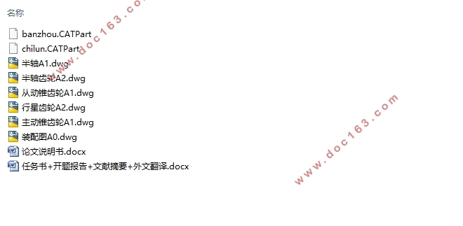
五菱荣光驱动桥的设计(含CAD零件图装配图)(任务书,开题报告,文献摘要,外文翻译,论文10000字,CAD图纸6张)
摘要
汽车在行驶的过程中,左右车轮的工作状况经常是不同的。比如汽车在转弯时,内外两个车轮在相同的时间里滚过的距离不同,这就需要汽车为两个车轮提供不同的转速,而驱动桥在这个过程中起了很重要的作用。当汽车驶过凹凸不平的路面时,需要将汽车受到的冲击力传递给车身,驱动桥在这个过程中起了一个中间传递的作用。当汽车爬坡或者需要较大驱动力的时候,需要把发动机传出的力矩放大,除了变速器,驱动桥也起到了这样的作用。为了降低汽车的使用成本,高效率地传递能量是重要的举措,设计一个结构合理的驱动桥可以达到这一目标。
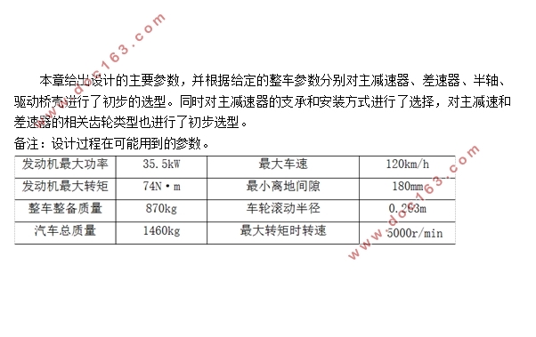
本文根据原始参数,对驱动桥主要零件进行匹配性结构选择,并且对主减速器等部件进行尺寸设计和强度校核,采用合理的工艺生产,使我设计的驱动桥能够满足五菱荣光的正常使用。
关键词:五菱荣光;差速器;半轴;主减速器
Abstract
During the course of the car, the working conditions of the left and right wheels are often different.Such as the car in the turn, inside and outside the two wheels in the same time the distance rolling different, which requires the car for the two wheels to provide different speed, and drive the bridge in this process played a very important role.When the car passing through the uneven road, the need to pass the impact of the car to the body, driving the bridge in the process played a role in the middle of the transfer.When the car climbing or need a larger driving force, the need to put the engine out of the torque amplification, in addition to the transmission, drive axle also played such a role.In order to reduce the use of the cost of the car, the efficient transmission of energy is an important measure, the design of a reasonable structure of the bridge can achieve this goal.
According to the original parameters of the main parts of drive axle by the matching structure, and the size of the design and strength check of the main reducer and other components, the production process and reasonable design, so that I can meet the driving bridge normal use of Wuling glory.
Keywords:Wuling glory; Differential mechanism; Half shaft; Main reducer
后桥总成初步选型设计
驱动桥结构形式主要取决于悬架形式,本课题针对微型车开发一款后驱动桥,对乘坐舒适性没有太多要求,以匹配发动机为主,该后桥初步选择非断开式驱动桥。
[来源:http://www.think58.com]


第1章 绪论 1
1.1 课题研究背景及意义 1
1.2 驱动桥总成概述 1
1.3 驱动桥分类 1
1.4 国内外研究现状 2
1.5 课题研究内容 2
第2章 后桥总成初步选型设计 3 [资料来源:www.THINK58.com]
2.1 主减速器结构方案确定 3
2.1.1主减速器齿轮的类型的选择 3
2.1.2 主减速器主动锥齿轮的支承形式及安装方式的选择 3
2.1.3 从动锥齿轮的支承方式和安装方式的选择 4
2.1.4 主减速器的轴承预紧及齿轮啮合调整 4
2.1.5 主减速器的减速形式 4
2.2差速器结构方案的确定 4
2.3 半轴型式的确定 5
2.4 桥壳型式的确定 5
2.5 本章小结 5
第3章 主减速器设计 7
3.1 主减速比的确定 7
3.2 主减速器齿轮计算载荷的确定 7
3.3 齿轮设计 8
3.3.1齿数的选择 8
3.3.2 节圆直径地选择 8
3.3.3 设计齿轮端面模数 9
3.3.4 齿面宽的选择 9
3.3.5 确定锥齿轮螺旋方向 9
3.3.6 螺旋角 的选择 9
3.3.7 法向压力角的选择 9
3.4 主、从锥齿轮的尺寸设计与强度校核 9
3.4.1 主、从动螺旋锥齿轮的几何尺寸设计 9
3.4.2 锥齿轮的强度校核 11
3.5 齿轮的材料选择及热处理 13
3.6 主减速器轴承设计 14
3.6.1 主动齿轮的受力分析 14
3.6.2 主减速器轴承载荷的计算 15
3.7 主减速器的润滑 17
3.8 本章小结 17
第4章 差速器设计 17
4.1 概述 18
4.2 行星齿轮差速器设计 18
4.2.1 差速器齿轮的参数设计 18
4.2.2差速器齿轮的几何尺寸计算与强度计算 19
4.3 本章小结 22
第5章 半轴设计 22
5.1 概述 23
5.2 半轴的设计与计算 23
5.2.1半浮式半轴的设计计算 23
5.2.2 半轴结构和工艺设计 24 [资料来源:http://think58.com]
5.3 本章小结 25
第6章 驱动桥桥壳的设计 25
第7章 结论 26
参考文献 27
附录A 28
致谢 29 [来源:http://think58.com]
上一篇:电动汽车的有序充电策略研究
