基于行驶工况的电动汽车动力转换特性研究(含CAD零件装配图)

1.无需注册登录,支付后按照提示操作即可获取该资料.
2.资料以网页介绍的为准,下载后不会有水印.资料仅供学习参考之用.
密 惠 保
基于行驶工况的电动汽车动力转换特性研究(含CAD零件装配图)(任务书,开题报告,论文说明书11000字,CAD图14张)
摘要
由于能源短缺和环境污染越来越严重,发展新能源汽车已是大势所趋。在政府政策的支持下,新能源专用汽车得到了较好的发展。环卫车作为专用车的一种,在保证城市干净清洁中发挥着不可替代的作用。
本文以一款7吨重纯电动环卫车为研究对象,设计了动力转换系统方案,对其动力传递系统关键部件进行了参数匹配和选型。具体的工作如下:
(1)对其驱动电机及动力电池进行了参数匹配与选型,以保证能满足纯电动环卫车整车的动力性和经济性要求。
(2)对不同行驶工况下该车的动力需求进行了计算,包括整车需要的功率和转矩
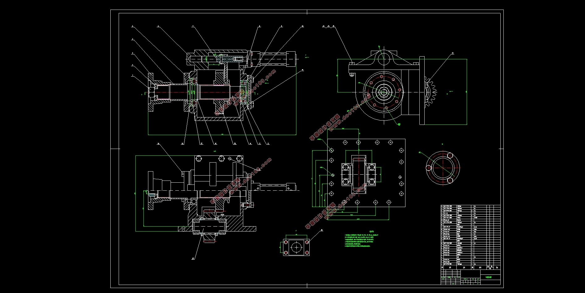
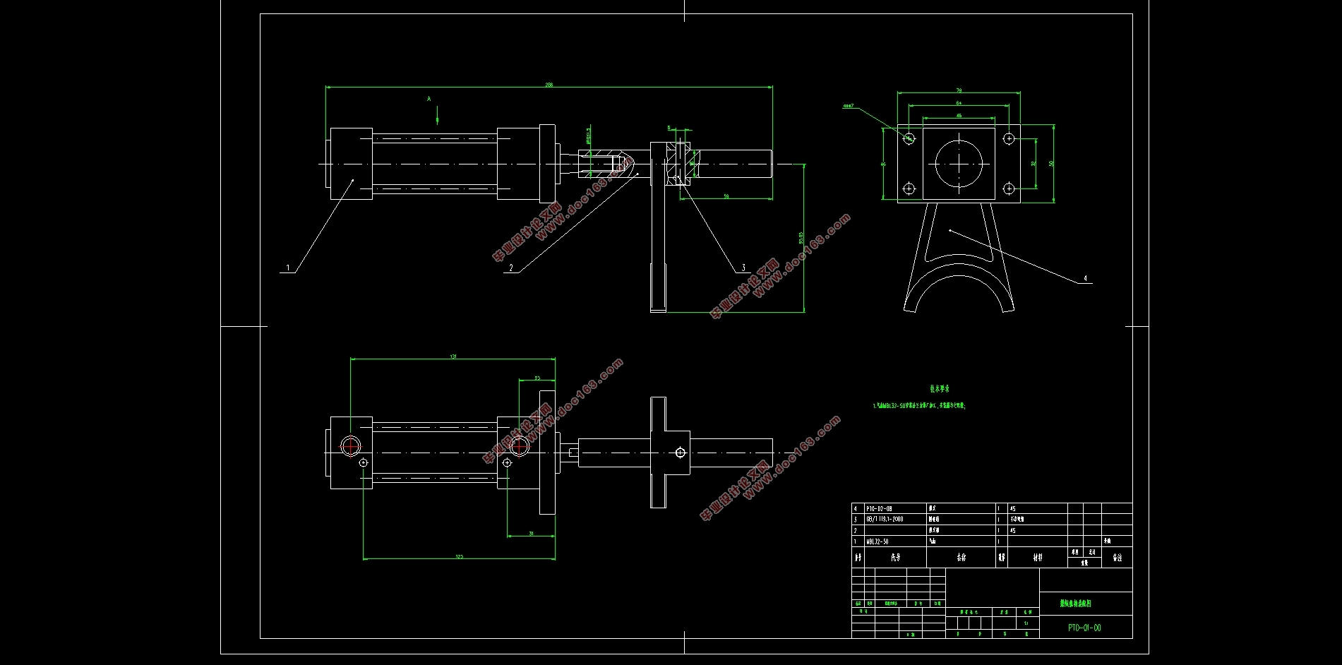
(3)设计了一款从变速器中间轴取力的取力器,对取力器的整体方案、齿轮、轴进行了设计。
关键词:纯电动环卫车;动力传动系统;行驶工况;电机;取力器
Abstract
Due to energy shortages and environmental pollution, the development of new energy vehicles is a general trend. With the support of government policies, new energy special vehicles have been well developed. As one of the special vehicles, sanitation vehicles play an irreplaceable role in ensuring clean and clean cities. [资料来源:www.THINK58.com]
In this paper, a 7-ton heavy-duty electric sanitation vehicle is taken as the research object, and the power conversion system scheme is designed. The key components of the power transmission system are matched and selected. The specific work is as follows:
(1) Parameter matching and selection of the drive motor and power battery are carried out to ensure the power and economy requirements of the pure electric sanitation vehicle.
(2) Calculate the power demand of the vehicle under different driving conditions, including the power and torque required by the vehicle.
(3) A power take-off device for taking force from the intermediate shaft of the transmission was designed, and the overall scheme, gear and shaft of the power take-off were designed.
Key words: pure electric sanitation vehicle; power transmission system; driving condition; motor; power take-off
[资料来源:http://THINK58.com]


目录
第1章 绪论 1
1.1选题的目的及意义 1
1.2国内外研究现状 1
1.2.1国外研究现状 1
1.2.2国内研究现状 2
1.3本章小结 2
[来源:http://think58.com]
第2章 行驶工况对电机效率的影响综述 3
2.1电动机的外特性 3
2.2行驶工况对电机效率的影响 3
2.3本章小结 4
第3章 动力转换系统方案设计 5
3.1驱动电机系统 5
3.1.1驱动电机的选型 5
3.1.2驱动电机参数匹配 5
3.2动力电池系统 8
3.2.1动力电池参数设计 8
3.2.2动力电池选型 10
3.3 本章小结 10
第4章取力器设计 11
4.1取力器简介 11
4.1.1取力器的作用 11
4.1.2取力器的分类 11
4.2取力器设计方案 11
4.2.1取力器壳体 11
4.2.2取力器操纵机构 11
4.3取力器齿轮设计 12
4.3.1二轴齿轮设计 12
4.3.2一轴齿轮设计 12
[资料来源:http://THINK58.com]
4.4取力器中心距 13
4.5取力器轴的设计 13
4.6本章小结 13
第5章 不同行驶工况下的动力需求计算 14
5.1无坡度工况 14
5.2极限作业坡度工况 14
5.3最大爬坡度工况 15
5.4本章小结 15
第6章 全文总结与工作展望 16
6.1全文总结 16
6.2工作展望 16
参考文献 17
致谢 19 [资料来源:www.THINK58.com]
上一篇:新能源汽车轮毂电驱动系统结构设计(含CAD零件装配图)
下一篇:商用车鼓式制动器制动效能监控系统设计(含CAD零件装配图,CATIA三维图)
