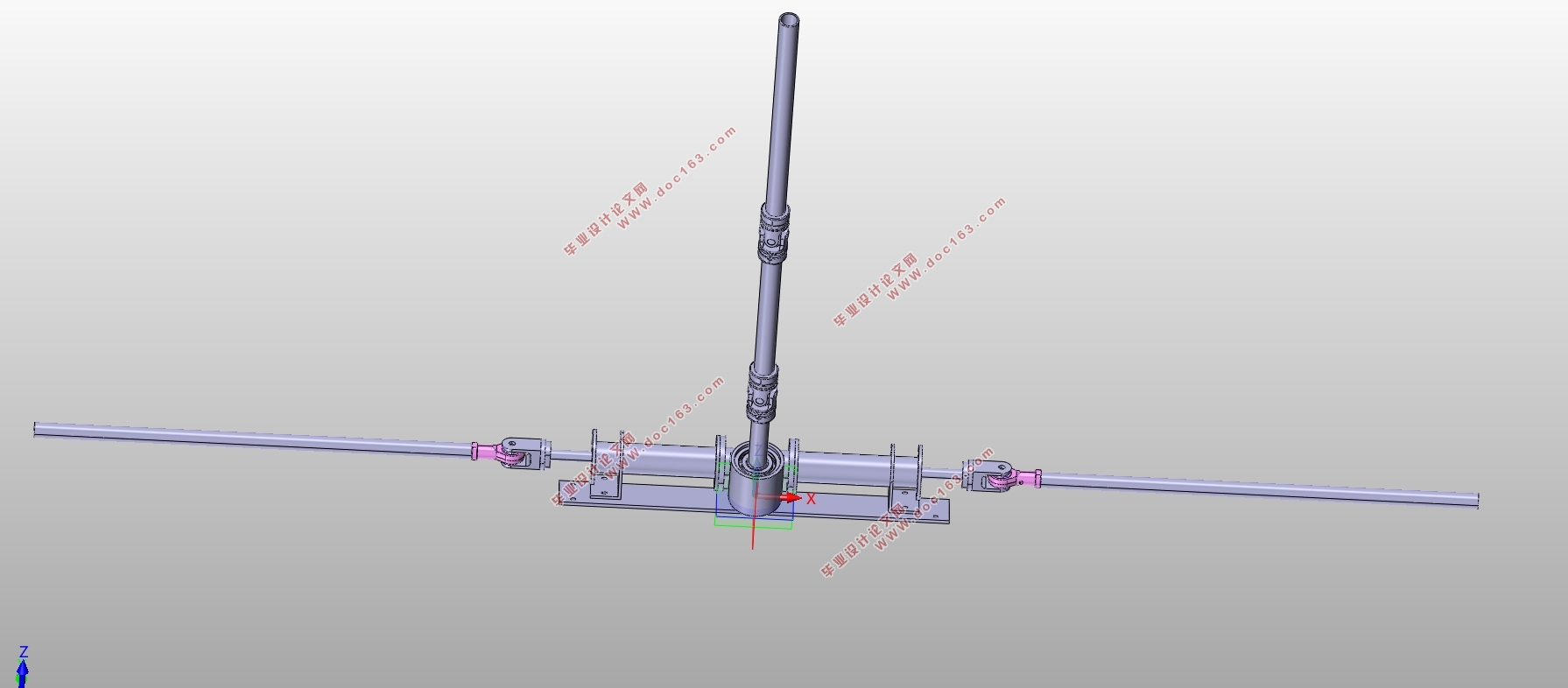
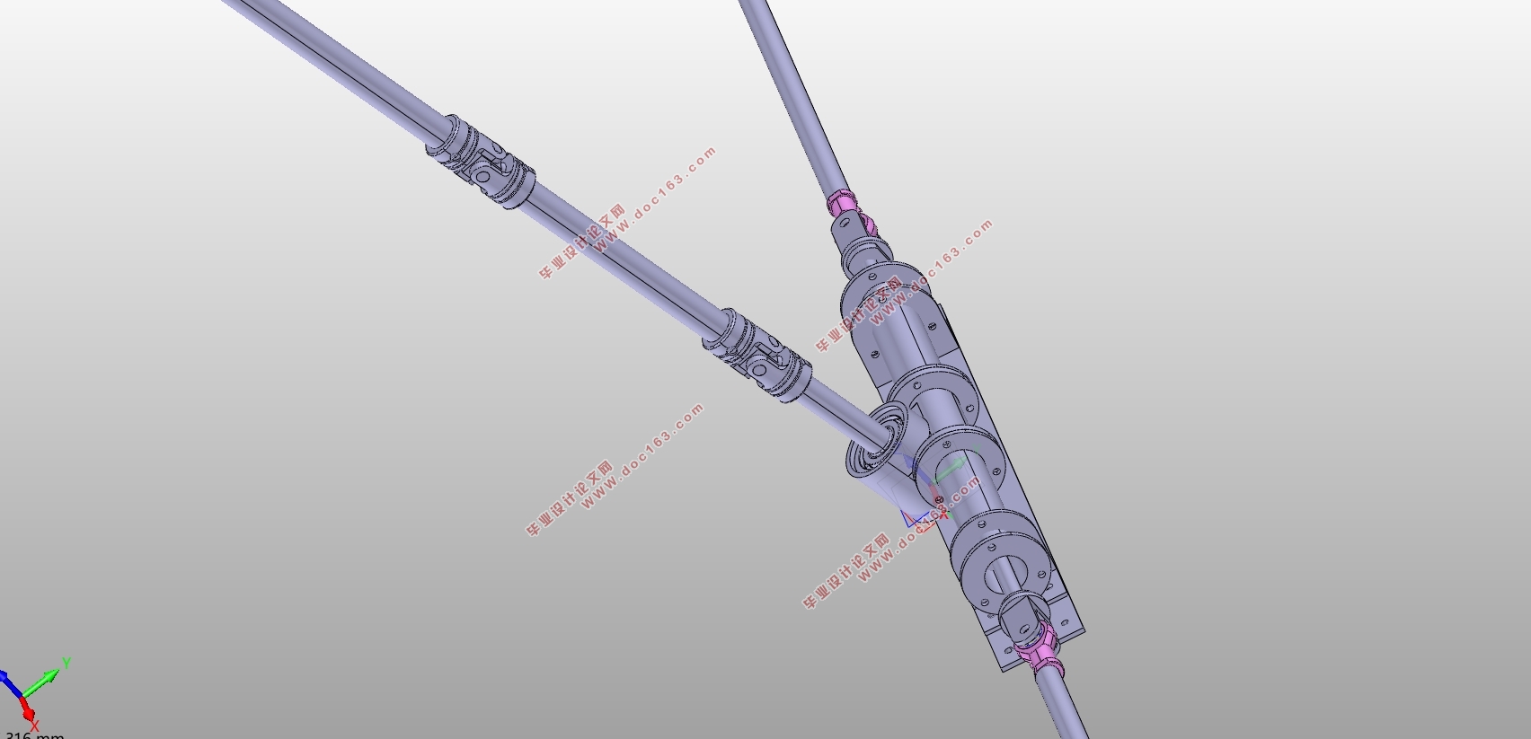
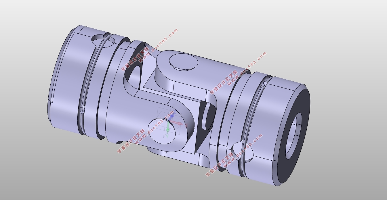
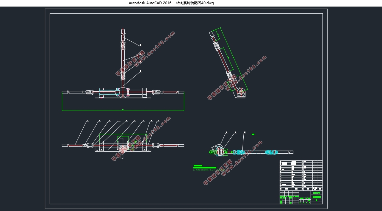
方程式赛车转向系统设计(含CAD零件图装配图,CATIA三维图)

1.无需注册登录,支付后按照提示操作即可获取该资料.
2.资料以网页介绍的为准,下载后不会有水印.资料仅供学习参考之用.
密 惠 保
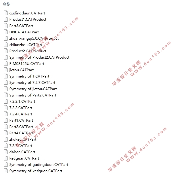
方程式赛车转向系统设计(含CAD零件图装配图,CATIA三维图)(任务书,开题报告,外文翻译,文献摘要,论文说明书13500字,CAD图5张,CATIA三维图)
摘 要
转向系统是方程式赛车中重要的组成部分,也是决定了赛车主动安全性的关键性系统,而转向器是方程式赛车转向系统中的最重要的组成部分,它的结构和质量严重关系到赛车的操纵稳定性。对于方程式赛车转向系统而言,由转向操控机构、转向器部分、转向传动机构共同组成整个转向系统,其中起到功能性作用的是转向器部分。齿轮齿条式转向器由于其本身的优点被广泛用于各类汽车的转向系统中,在本次方程式赛车转向系统的设计中也因其正效率高、结构简单、加工性好而选择齿轮齿条式转向器。此外,本文也着重强调了对转向梯形机构的设计与优化从而满足转向系统在结构上的要求。同时,大学生方程式赛车大赛与专业方程式赛车有所不同,根据其特殊性对赛车的结构与性能做出针对性的设计与调整,在满足2017年大赛规则的前提下同时满足方程式赛车的性能要求与强度要求。
关键词 方程式赛车 齿轮齿条式转向器 转向梯形 设计
Abstract
The steering system is one significant component of the systems of formula cars, and it is also the key system that determines the active safety of racing cars. The steering gear fuctions most within the steering system of the formula car. Its structure and quality are seriously related to the performance of handling and stability of the car. In the steering system of the formula car, it is mainly composed of by a steering transmission mechanism, a steering control mechanism and a steering gear,within which the steering system matters most. In power steering gears, rack and pinion steering gears are widely used in the steering systems of various types of automobiles due to their own advantages.In the design of this formula racing car steering system, they are also highly efficient, simple in structure, and easily-processed.As a result,it is obvious to choose a rack and pinion steering gear. In addition, this design also emphasizes the design and optimization of the steering trapezoidal mechanism to meet the structural requirements of the steering system. At the same time, the FSAE is different from that of professional Formula Racing. Accordingly to its particularity, the design and adjustment of the structure and performance of the racing car are tailored to meet the performance requirements of Formula Racing while satisfying the rules of the 2017 Contest.
[资料来源:http://www.THINK58.com]
key words Formula Racing;Rack and Pinion Steering Gear;Steering Trapezium;Design
确立基本参数
在构建转向梯形结构优化模型之前,首先确立方程式赛车基本参数:
主销间距K=1077mm
轴距wheelbase=1550mm
轮距thread=1230mm
最小转弯半径Rmin=3500
另外,主销偏移距KP=(thread-K)/2=76.5mm
[版权所有:http://think58.com]

 [资料来源:THINK58.com]

目录
摘 要 3
Abstract 4
目录 5
第1章 绪论 1
1.1大学生方程式赛车大赛 (FSAE)概述 1
1.1.1 FSAE简介 1
1.1.2 国内外发展与现状 1
1.1.3设计的基本内容 3
1.1.4 拟用技术方案及措施 3
第2章 转向系统的组成 4
2.1 赛车转向系概述 4
2.2转向系统的基本构成 4
[来源:http://think58.com]
2.3 转向操纵机构 4
2.4 转向传动机构 6
2.5 机械式转向器方案分析 6
2.5.1 齿轮齿条式转向器 6
2.5.2 其他形式的转向器 7
2.5.3 对于各种形式的转向器的选择 8
2.6 赛车转向系统传动比分析 8
2.7 转向梯形机构的分析与选择 9
2.7.1 转向梯形机构的选择 9
2.7.2 断开式转向梯形断开点位置的确定 10
第3章 转向器的选择 12
3.1 转向器的效率 12
3.1.1 转向器的正效率η+ 12
3.1.2 转向器的逆效率η- 13
3.2 转向器传动副的传动间隙Δt 14
第4章 转向梯形的设计与优化,相关参数的确定 16
4.1 确立基本参数 16
4.2 左右转向轮关系 16
4.2.1 理想的左右转向轮转角关系 16
4.2.2 优化目标函数的确定 17 [版权所有:http://think58.com]
4.3 构建转向梯形结构优化的MATLAB程序 18
4.3.1 优化模型的MATLAB表达 18
4.3.2 约束模型的MATLAB表达 19
4.3.3 优化结果 20
4.4横拉杆结构参数及强度校核 22
4.5 转向操控机构 22
4.5.1 传动轴的直径及其校核 22
4.5.2 万向节的选型 24
4.6 转向器的主要零件参数确定及其校核 25
4.6.1 转向器壳体 25
4.6.2 齿轮轴与齿条 25
4.6.3 轴承的设计 28
4.7 与车架前环焊接的轴的设计 29
4.7.1 设计方案的提出 29
4.7.2 三种方案的比较 30
第5章 结论 33
参考文献 34
附录 35
附录A 转向梯形优化MATLAB程序 35
附件B 转向系统三维建模及二维图纸 37
致谢 40 [来源:http://www.think58.com]
上一篇:承载200kg电动轮设计(含CAD图,SolidWorks三维图)(英文版)
下一篇:桑塔纳1.6L轿车制动系统设计(英文版)(含CAD零件装配图)
