消防车用分动箱结构设计与优化(含CAD零件图装配图)

1.无需注册登录,支付后按照提示操作即可获取该资料.
2.资料以网页介绍的为准,下载后不会有水印.资料仅供学习参考之用.
密 惠 保
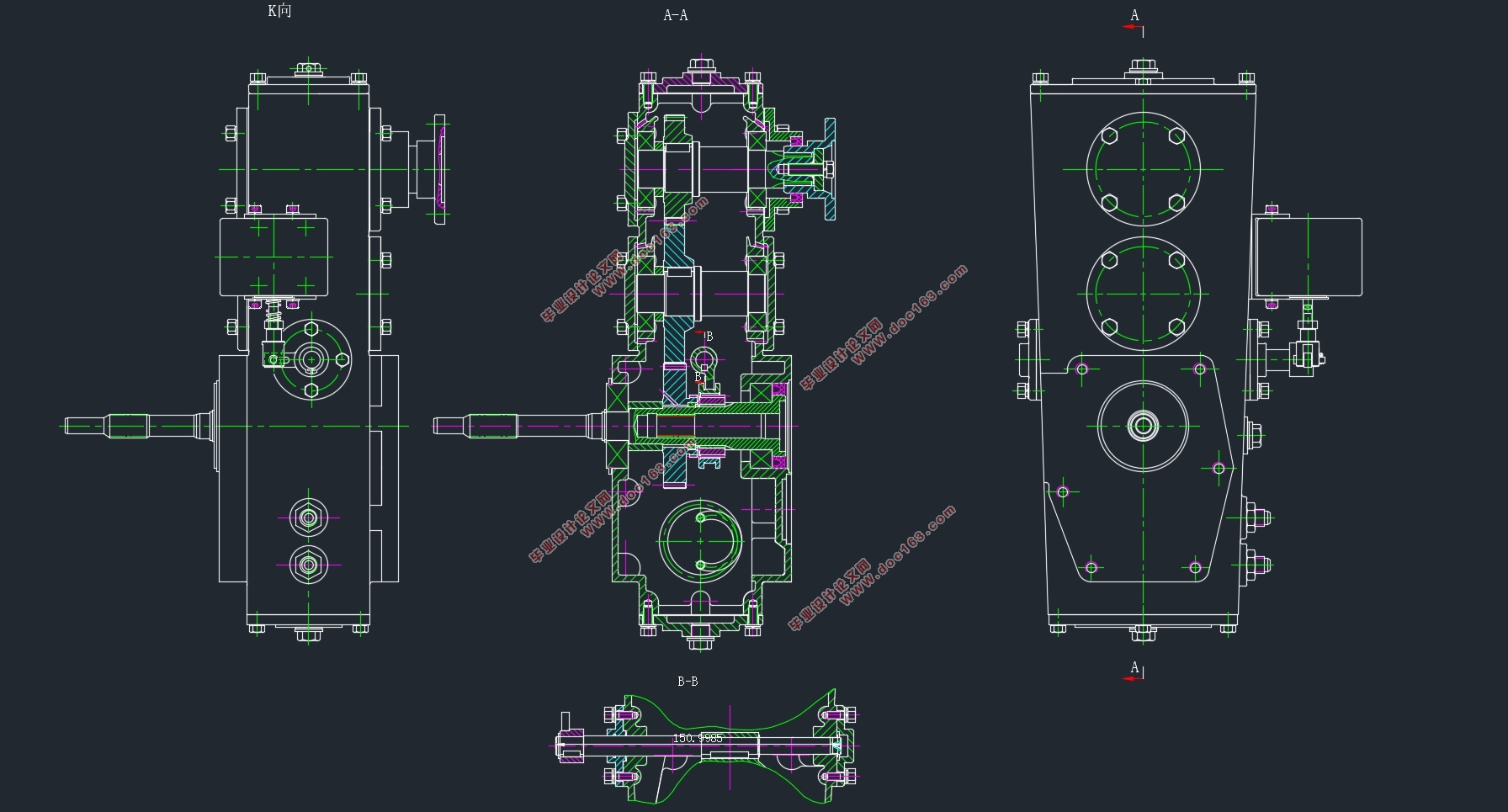
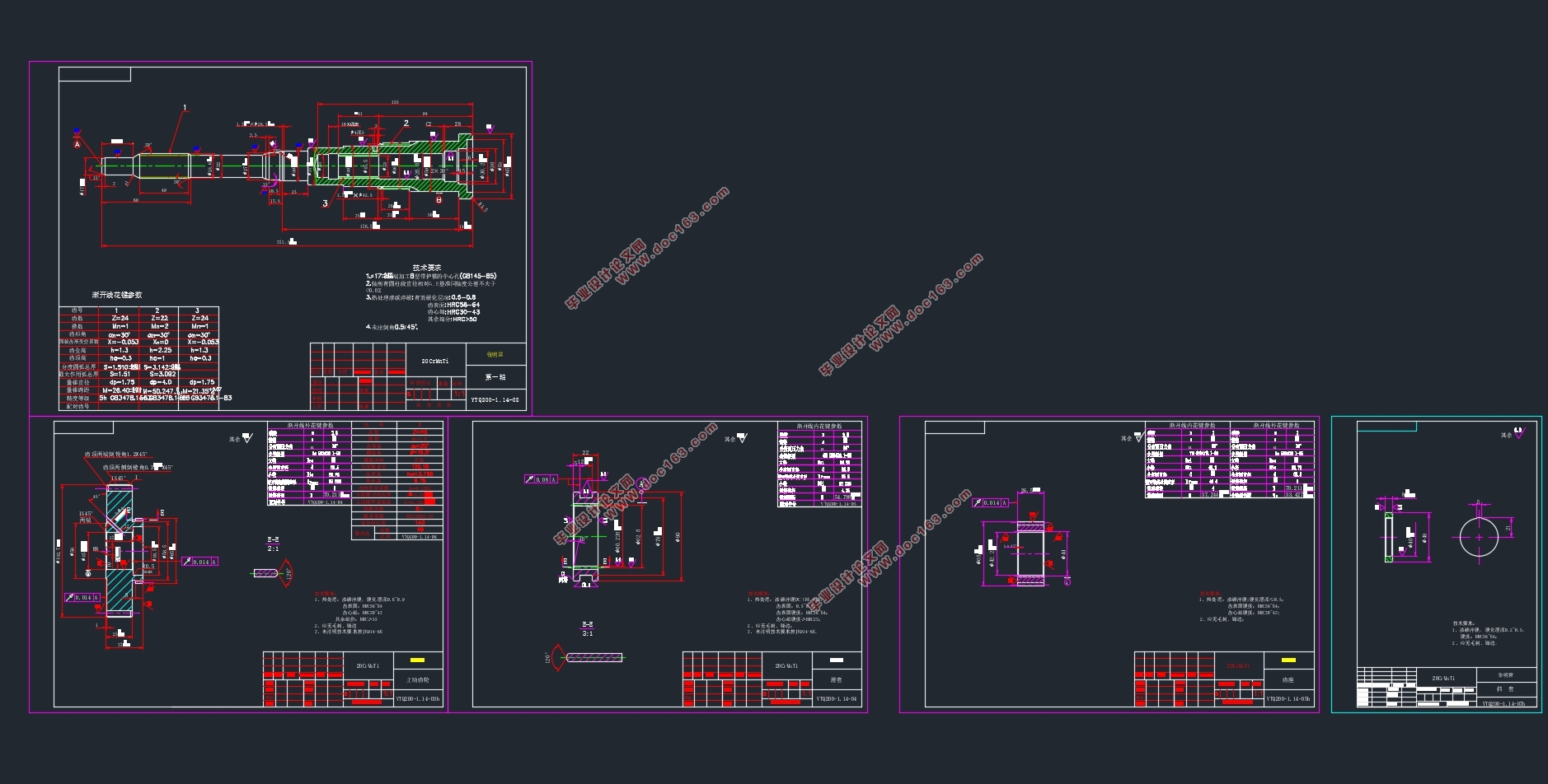
消防车用分动箱结构设计与优化(含CAD零件图装配图)(开题报告,论文说明书10400字,CAD图6张)
摘要
分动箱是非常重要的一部分在专用车辆的传动系统中,在消防车的动力传动、动力分配等方面也是有着举足轻重的作用。分动箱技术是解决车辆动力问题的核心技术,国内外的机构以及学者都投入了大量的时间和资金进行研究,但是任然面临着不少问题,本文针对分动箱的齿轮设计和有限元分析进行了设计和研究,具体如下:
(1)介绍了国内外对于分动箱以及齿轮啮合系统的发展现状、研究水平以及未来主要的发展趋势,分析分动箱主要结构、计算各传动比及齿轮参数。
(2)主要设计了分动箱的主要结构,对齿轮结构进行了设计,计算了强度、几何尺寸等参数。
(3)最后,设计尺寸并通过ANSYS Workbench软件对分动箱的主要部件的有限元模型进行了模态分析,得到应力集中和变形情况,验证其强度等要素是否可以满足标准。
关键词:分动箱齿轮设计模态分析
Abstract
In the transmission system of a dedicated vehicle, the transfer case is a very important part and is an integral part of the fire engine for various output power. The analysis of boxing technology is the core technology to solve the problem of vehicle power, domestic and foreign institutions and scholars have invested a lot of time and money to study, but still faced with a lot of problems, this paper for the split box gear design and finite element The analysis was carried out in the design and research, as follows: [资料来源:http://www.THINK58.com]
(1)This paper summarizes the current situation, the research level and the main development trend of the moving box and the gear meshing system at home and abroad, analyzes the main structure of the transfer case, calculates the transmission ratio and the gear parameters, designs the dimensions and makes the key part Finite element analysis.
(2)The main structure of the transfer case is designed, the gear structure is designed, the strength, the geometric size and so on are calculated.
(3)Finally, the finite element model of the main components of the transfer case is analyzed by modal analysis, and the stress concentration and deformation are obtained. It is verified whether the strength and other factors can meet the standard.
Key words: transfer case;gear design;modal analysis
[资料来源:THINK58.com]


目录
摘要 I
Abstract II
第一章 绪论 5
1.1课题研究的目的以及意义 5
1.2国内外研究现状 2
1.2.1国外研究概况 3
1.2.2国内研究概况 5
1.3发展趋势 8
1.4分动箱的设计要求 9
1.5本章小结 9
第二章 参数计算 10
2.1分动箱概述 10
2.2 分动箱的工作情况 11 [资料来源:http://www.THINK58.com]
2.3参数计算 12
2.3.1 总传动比和传动比分配计算 12
2.3.2各轴转速计算 13
2.3.3各轴输入功率计算 13
2.3.4各轴转矩计算 14
2.4本章小结 14
第三章 齿轮设计 15
3.1齿轮的选定 15
3.1.1材料的选择 15
3.1.2齿数的选定 15
3.2按齿面接触强度设计 15
3.2.1 计算公式及参数 15
3.2.2 设计计算 17
3.3按齿根弯曲强度设计 18
3.3.1 计算公式及参数的选定 18
3.3.2设计计算 21
3.4几何尺寸计算 22
3.5齿轮的结构设计 22
3.6本章小结 24
第四章 取力器三维建模与模态分析 25
4.1取力器三维建模 25
4.1.1模型的建立与简化 25 [资料来源:http://think58.com]
4.1.2 零部件材料属性 26
4.2取力器模态分析 26
4.2.1网格划分及质量检查 27
4.3有限元模态计算 28
4.3.1箱体模态分析 29
4.3.2齿轮啮合系统网格化分 30
4.4本章小结 32
第五章 总结与展望 33
5.1总结 33
5.2展望 33
致谢 34
参考文献 35
[资料来源:http://www.THINK58.com]
上一篇:汽车磁流变液力缓速器制动性能分析研究(含CAD零件图装配图)
下一篇:全功率燃料电池汽车整车热管理系统设计与分析(含CAD图)
