某型汽车仪表盘注塑模具设计(含CAD图,UG三维图)
1.无需注册登录,支付后按照提示操作即可获取该资料.
2.资料以网页介绍的为准,下载后不会有水印.资料仅供学习参考之用.
密 惠 保
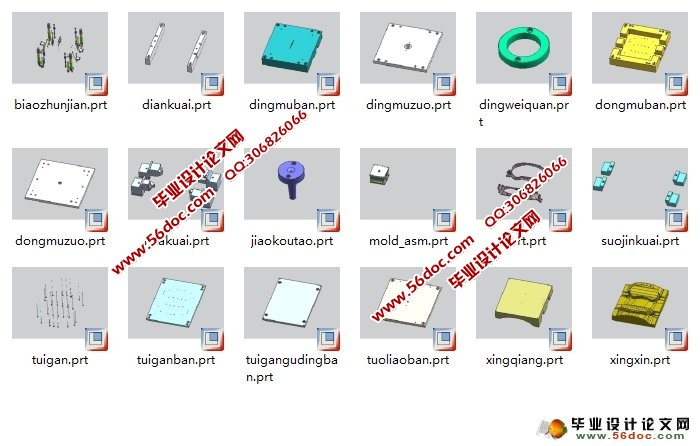
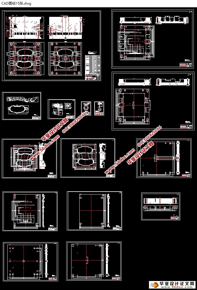
某型汽车仪表盘注塑模具设计(含CAD图,UG三维图)(任务书,开题报告,外文翻译,论文说明书8500字,CAD图纸15张,UG三维图18张)
摘要
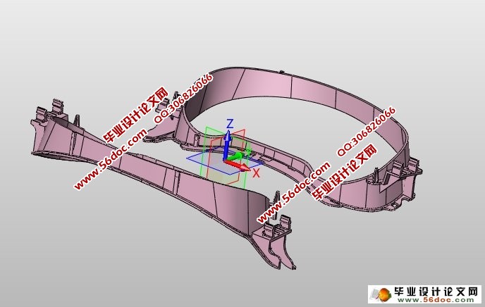
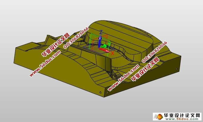
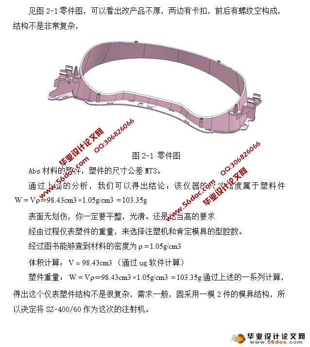
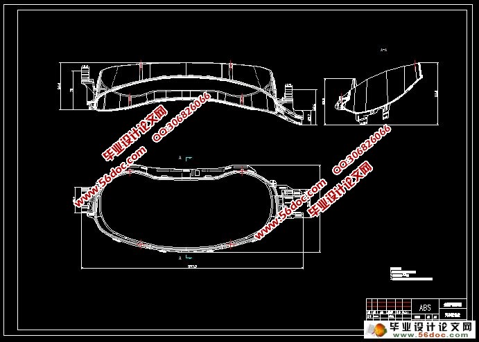
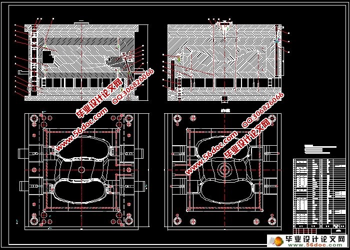
本次毕业设计论文,主要设计的是汽车仪表部件,仪表主要有4部分组成,透明罩子,塑料外壳,中壳和底壳组成。这次设计的是仪表的前壳,前壳主要是用卡扣,螺纹等连接底壳。在计划的过程当中,按照仪表的年产,选择及格的注塑机。选择好合适的注塑机,需要了解塑件的材料的性能,以及加工要注意的地方。经由过程计较选择适合的模板架。计划主流道,分流道,肯定浇口位置,以后计算出型芯,型腔的尺寸,冷却线路的计划。之后用ug8.0计划出模具的零件图,在装配起来。然后用ug软件,画出模具的装配图,以及各个部位的零件图,最后导出cad格式。论文书写的时候,需要把整个模具设计的思路,计算公式写清楚。
关键词:汽车仪表盘、ug、设计
A certain type of car dashboard injection mold design
Abstract
This graduation thesis design, and design is the main instrument automobile parts, instruments are mainly composed of four parts, transparent cover, plastic shell, the shell and the bottom composition. Shell is mainly used snap, design before a thread and other connection bottom case is the front housing of the equipment. In the design process, according to an annual output of the instrument, the selection of qualified injection molding machine.Choosing suitable injection molding machine, you need to understand the properties of the material of the plastic parts, and local processing to be noted. Select the frame of the appropriate template by calculating. Design sprue, runner, gate location is determined. After calculating the core, cavity size, cooling line design.The assembly, .Followed by ug8.0 design mold parts of the drawing.Then ug software, draw the mold assembly drawing, and all parts of the parts diagram, and finally export cad format. Thesis writing, the need for the entire mold design ideas, calculated to write clearly. [来源:http://www.think58.com]
Keywords: template, standard parts, stripping out the system design
[版权所有:http://think58.com]
目 录
摘要 1
ABSTRACT 2
第1章 引言 3
1.1 注塑模具在汽车领域 3
1.2 仪表的介绍 4
第2章 产品分析 5
2.1 产品分析 5
2.2 塑件材料的选择 7
2.2.11 质料ABS的注塑成型参数 7
2.2.2 材料ABS性能 8
第3章 注射模具结构设计 9
3.1 型腔数目的确定 9
3.2 型腔的分布 9
3.3 分型面的设计 10
3.4 浇注系统结构设计 10
3.4.1 主流道 10
3.4.2 分流道设计 11
3.4.3 选择浇口的形状和位置 11
3.4.4 剪切速率的校核 12
3.4.5 浇道剪切速度的确认 12
3.4.6 检测剪切速率 13
3.5 成型零件结构设计 13
3.5.1 定模的结构设计 13
3.5.2 动模的结构设计 13
3.5.3 腔体侧壁厚度计算 13
3.5.4 腔和芯的工作尺寸的计算 14
3.6 推杆机构设计 15
3.6.1 脱模机构的选用原则 15
3.6.2 脱模力的计算 15
3.6.3 推杆的设计 16
第4章 注塑机校核 17
4.1 模具闭合高度的确定 17
4.2 由锁模力选定注射机 17
4.3 最大注塑量的校核 18
4.4 锁模力的校核 18
4.5 塑化能力的校核 18
第5章 模具的试模与修模 19
5.1 粘着模腔 19
5.2 粘着主流道 19
5.3 成型缺陷 19
第6章 侧抽芯机构 21
6.1 斜导柱设计 21
6.2 滑槽的设计 23
6.3 楔紧设计 23
第7章 模具工作原理 25
结论和展望 26
致谢 27
参考文献 28
附件 29
附件
附件-1垫块
附件-2定模板
附件-3定模座
附件-4动模板
附件-5动模座
附件-6滑块
附件-7锁紧块
附件-8推杆
附件-9推杆板
附件-10推杆固定板
附件-11脱料板
附件-12装配图
[资料来源:THINK58.com]
下一篇:货车自动紧绳装置设计(含SolidWorks三维图)
