
武汉市光谷C区排水工程的设计(含CAD图)
1.无需注册登录,支付后按照提示操作即可获取该资料.
2.资料以网页介绍的为准,下载后不会有水印.资料仅供学习参考之用.
密 惠 保
武汉市光谷C区排水工程的设计(含CAD图)(任务书,开题报告,论文说明书28000字,CAD图7张)
摘 要
排水工程设计是城市规划不可或缺的一部分。本设计的任务是完成湖北省武汉市光谷C区的排水工程设计。排水工程涉及范围囊括:雨、污水管网工程与污水处理厂工程。
武汉市光谷C区总体地势西高东低,南北高中间低,中部为里沟港水域,东部为严家湖水域,两水域相连,常水位标高18米。
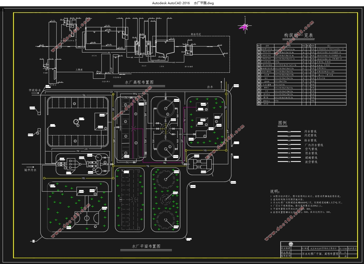
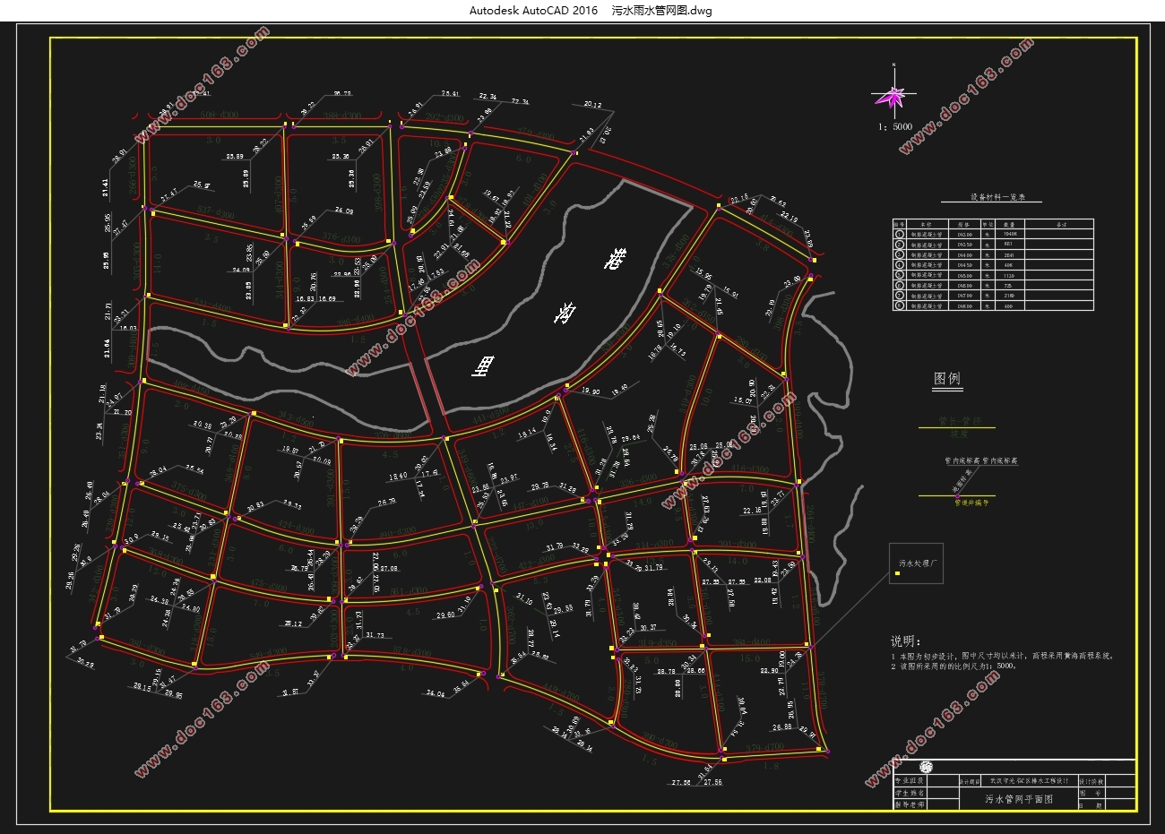
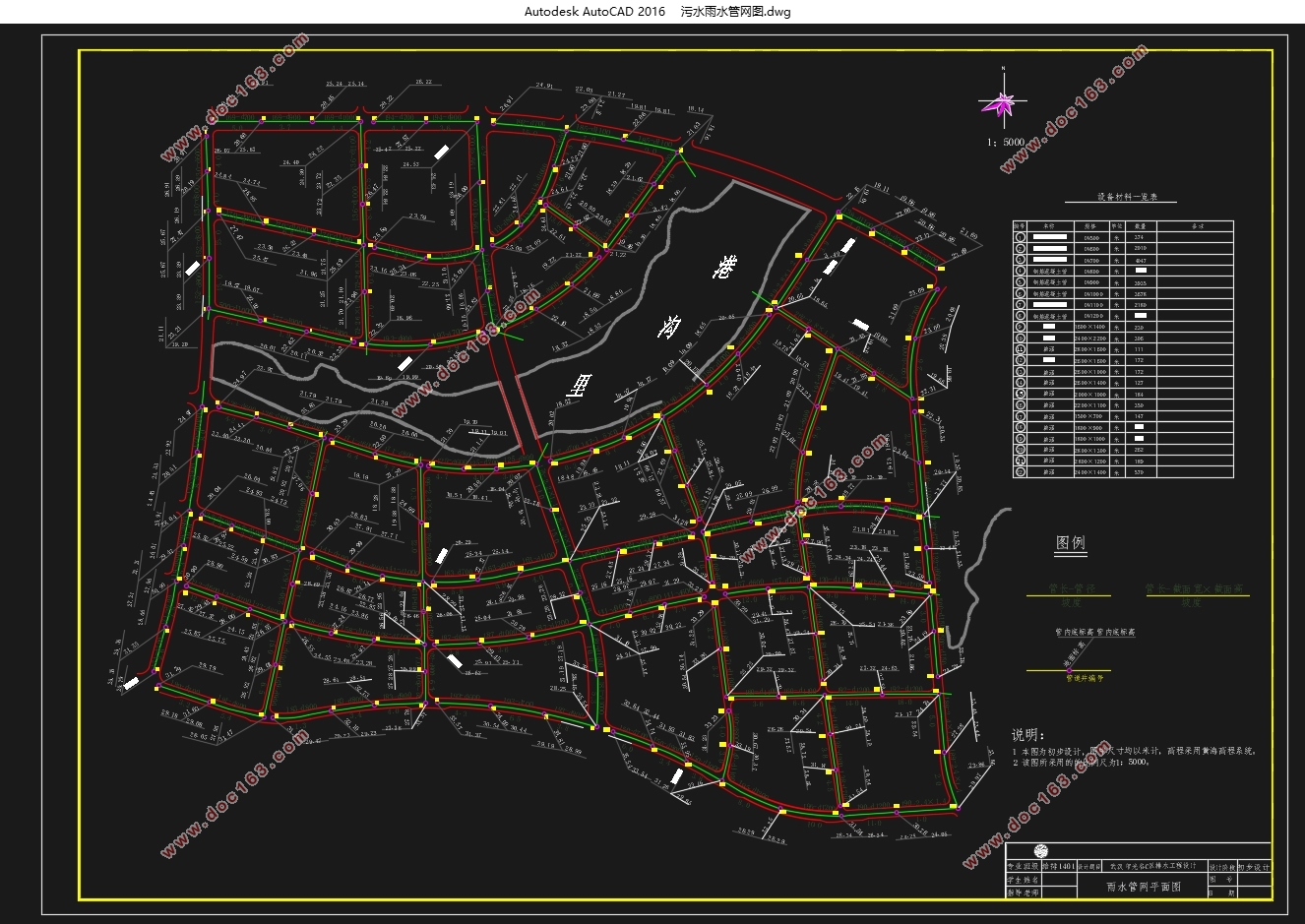
根据该区的实际情况,排水管网采用完全分流制系统。污水整体分两部分收集,一部分为里沟港北部,另一部分在里沟港南部,两部分雨水收集后输送至东南部的污水处理厂进行处理后排放至严家湖。雨水依据就近排放的原则,共设置13根雨水干管,分别收集后就近排放到附近水体。
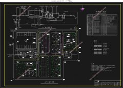
根据流域特点和主导风向,污水处理厂定址于光谷C区的东南部,近期规模为8210m3/d,远期规模为1.4万m3/d。根据处理水特点和出水水质要求,采用一级A处理要求,核心生物处理工艺选择A2/O法同步脱氮除磷工艺,主要工艺流程为中格栅→提升泵房→细格栅→沉砂池→AAO生化池→二沉池→消毒池→出水。
根据所提供的原始资料,我在本设计中完成了光谷C区排水管道系统、污水处理厂构(建)筑物的设计计算,绘制图纸8张(A1,包括一张墨线图和手画图),完成说明书、计算书各一份。 [来源:http://think58.com]
关键词:光谷C区、排水系统、污水处理、A2/O法
Abstract
Drainage engineering design is an integral part of urban planning. The task of this design is to complete the drainage engineering design of Guang gu C District, Wuhan City, Hubei province. Drainage works include: rain, sewage pipe network works and sewage treatment works.
The C area of Guang gu, Wuhan, is high East and low in the west, middle and low in North and south. In the middle is Li Gou Port waters, the East is Yan Jia lake water, two waters are connected, and the water level is 18 meters high.
According to the actual situation of the area, the fully distributary system is adopted in the drainage network. The sewage is collected in two parts, one is the north of Li Gou Port, the other is in the south of the Li Gou Port. The two part of the rainwater is transported to the sewage treatment plant in the southeast, and then discharged to Yan Jia lake. According to the principle of nearby discharge, rainwater altogether set up 13 rain water trunk pipes, which were collected and discharged to nearby water bodies nearby.
[版权所有:http://think58.com]
According to the characteristics and dominant wind direction of the basin, the sewage treatment plant is located in the southeastern part of Guang gu C area, with a recent scale of 8210m3/d and a long-term scale of 13 thousand m3/d. According to the characteristics of water treatment and water quality requirements, using the first grade A treatment requirements, the core biological treatment process selected A2/O method for simultaneous nitrogen and phosphorus removal, the main process flow is the middle grid, the lifting pump room, the fine grille, the sand sedimentation tank, the AAO biochemical pool, the two sink, the disinfection pool and the effluent.
According to the original information provided, I completed the design and calculation of the drainage pipe system of Guang gu C and the construction of the sewage treatment plant in this design, drawing 8 drawings (A1, including a ink drawing and hand drawing), and completing one of the instructions and the number of calculations.
Key words:Guang gu C area, drainage system, sewage treatment , A2/O method
2.1 设计原始资料
2.1.1 城市概况
武汉市光谷C区位于武汉市洪山区高新二路南侧,总体面积412公顷。根据规划,该区域近期人口密度为每平方千米7000人,远期人口密度为每平方千米1000人。目前该区域多为居住区,工业相对不发达,污水主要是生活污水,工业污水量不大。
2.1.2 自然条件
(1)地形资料
武汉市光谷C区总体地势西高东低,中部被里沟港穿过,因此南北高,中间低。
(2)气象资料
属大陆性季风气候,由于武汉市属于特大城市,夏季热岛效应明显,夏季平均气温在30℃以上,冬季平均气温偏低,在10℃左右。全年平均气温25℃。
主导风向为西南风
里沟港及严家湖常水位为18m
2.1.3 排水现状
光谷C区是武汉城区边陲地区未开发的地带,工业不发达,区内尚无污水管道系统和雨水管道系统,需建设完整的排水管道收集系统,做到雨、污分流,将污水收集并输送到污水处理厂。
[资料来源:http://THINK58.com]

目 录
第1章 绪论 1
1.1 设计任务 1
[版权所有:http://think58.com]
1.2 设计成果 1
第2章 设计说明书 2
2.1 设计原始资料 2
2.1.1 城市概况 2
2.1.2 自然条件 2
2.1.3 排水现状 2
2.2 排水方案设计 2
2.2.1 排水体制的选择 2
2.2.2 污水管网设计 3
2.2.3 雨水管网设计 3
2.3 污水处理设计 3
2.3.1 污水处理工艺的选择 3
2.3.2 工艺流程的确定 3
2.3.3 污水处理构筑物 3
2.4 污泥处理设计 5
2.4.1 污泥处理基本方案 5
2.4.2 污泥处理构筑物 5
2.5 污水厂附属构筑物 6
2.5.1 面积规划 6
2.5.2 水厂定员 6
2.5.3 附属构筑物 6
2.6 污水厂的总体布置 7
2.6.1 污水厂平面布置 7
[资料来源:http://www.THINK58.com]
2.6.2 污水厂高程布置 7
2.7 排水工程运行成本估算 7
设计计算书 8
第3章 城市排水方案的确定及计算 8
3.1 排水系统体制的选择 8
3.2 污水管网设计 8
3.2.1 设计要点 8
3.2.2 管段流量及水力计算 8
3.3 雨水管网设计 9
3.3.1 管网定线 9
3.3.2 水力计算 9
第4章 城市污水处理方案的确定 12
4.1 污水处理方案选择原则 12
4.2 污水工艺流程选择 12
4.3 污水处理构筑物的选择 12
4.3.1 格栅 12
4.3.2 沉砂池 12
4.3.3 二沉池 12
4.3.4 消毒阶段 12
4.3.5 污泥浓缩脱水 13
4.3.6 计量设施 13
第5章 污水厂主体构筑物设计计算 14 [资料来源:THINK58.com]
5.1 设计原始资料 14
5.1.1 规模 14
5.1.2 设计流量 14
5.1.3进出水水质 15
5.2 泵前中格栅设计计算 16
5.2.1 设计参数 16
5.2.2设计计算 16
5.3 污水提升泵房的设计计算 17
5.3.1 设计要点 17
5.3.2 设计参数 17
5.3.3设计计算 17
5.4泵后细格栅的设计计算 19
5.4.1设计参数 19
5.4.2设计计算 20
5.5 沉砂池的设计计算 21
5.5.1 设计参数 21
5.5.2 设计计算 21
5.6 A2/O反应池设计计算 21
5.6.1 设计参数 21
5.6.2 设计计算 21
5.7 二沉池的设计计算 29
5.7.1 设计参数 29
5.7.2 设计计算 30
[资料来源:THINK58.com]
5.8 综合井的设计计算 33
5.8.1 设计要点 33
5.8.2设计参数 34
5.8.3设计计算 34
5.9 紫外线消毒 35
5.9.1 设计参数 35
5.9.2 设计计算 35
5.10 计量设施设计计算 36
5.10.1 设计参数 36
5.10.2 设计计算 36
5.11 污泥处理的设计计算 36
5.11.1 设计计算 36
第6章 污水厂附属构筑物设计计算 38
6.1 水厂总体面积的规划 38
6.2 水厂定员 38
6.3 水厂各构筑物及附属构筑物平面面积 38
第7章 污水处理厂的总体布置 39
7.1 污水处理厂平面布置 39
7.1.1 污水厂平面布置 39
7.2 污水处理厂高程布置 39
7.2.1 污水厂高程布置 39
第8章 排水工程运行成本估算 43 [资料来源:THINK58.com]
8.1 电动设备运行费用 43
8.2 药剂成本 43
总结 44
参考文献 45
致谢 47
附录 48 [来源:http://think58.com]