广州某办公楼辅楼暖通空调工程设计(含CAD图)

1.无需注册登录,支付后按照提示操作即可获取该资料.
2.资料以网页介绍的为准,下载后不会有水印.资料仅供学习参考之用.
密 惠 保
广州某办公楼辅楼暖通空调工程设计(含CAD图)(设计说明书19000字,CAD图纸14张,PDF图14张)
摘要
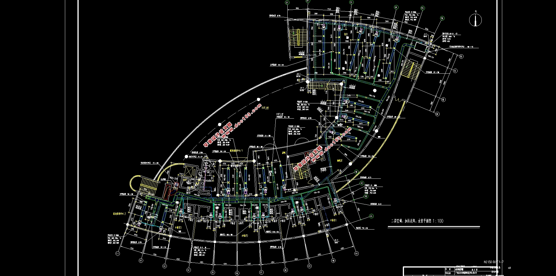
本设计地点为广州,建筑高度46.2m,建筑面积9200㎡,功能齐全。地下一层为设备用房,一层为商场、商务中心、厨房,二层为餐厅、酒吧,三至六层为客房标准层,七至十二层为办公会议层。
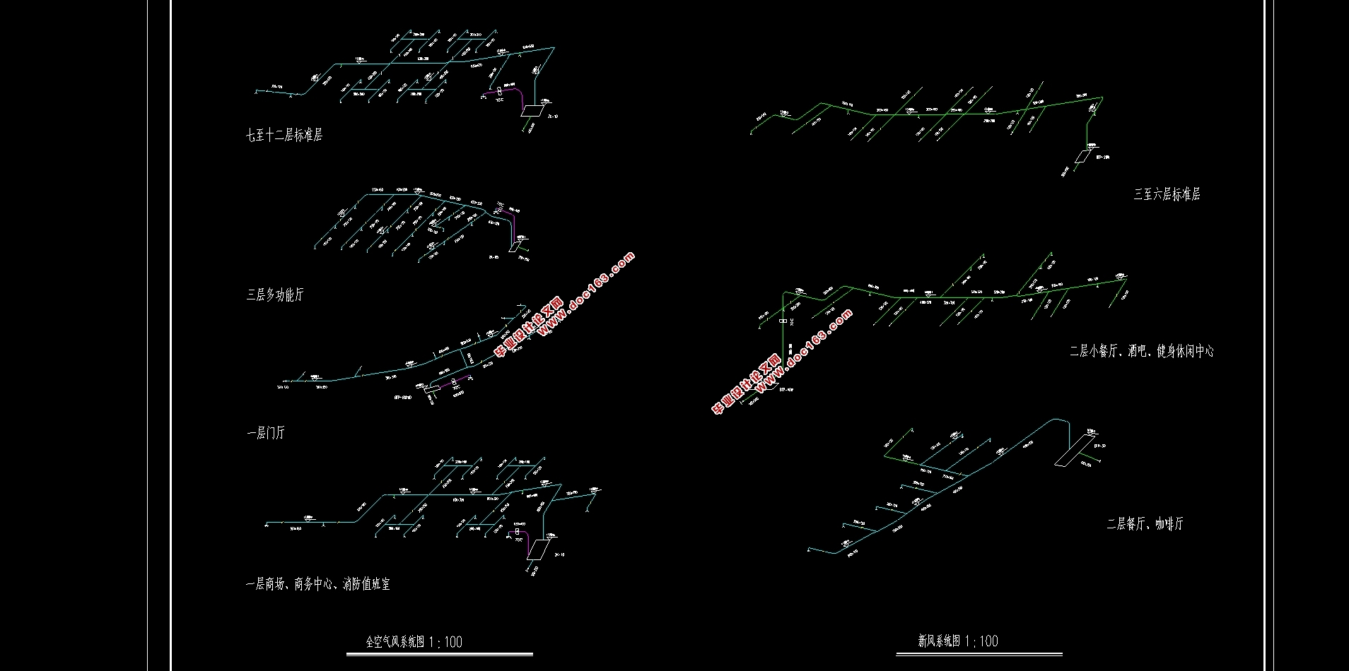
冷负荷计算采用谐波反应法,一层、三层多功能厅、七至十二层采用全空气处理机组,二至六层采用风盘加新风。供回水选用异程式两管制设计方式。风管水力计算采用推荐流速法,水系统水力计算采用推荐比摩阻法进行计算。冷热源选用空气源热泵,布置于裙房楼顶。地下一层以及一层厨房进行通风设计。防排烟部分,楼梯间自然通风,前室加压送风,其余房间均采用自然排烟。
关键词:谐波反应法 全空气系统 空气源热泵 加压送
HVAC Engineering Design of Auxiliary Building of an Office Building in Guangzhou
Abstract
The design site is Guangzhou, with a building height of 46.2m, with a building area of 9200㎡and complete functions.The underground floor is for equipment,the first floor is shopping mall, business center and kitchen, the second floor is restaurant and bar, the third to sixth floors are standard rooms, and the seventh to twelfth floors are office meeting floors. [来源:http://www.think58.com]
The cooling load is calculated by harmonic response method.The first floor, the third floor multi-function hall, the seventh to twelfth floor adopt the primary return air system, and the second to sixth floor adopt the fan coil unit plus fresh air system.The backwater supply adopts two different control design methods.The design calculation mode of air duct is chosen to calculate the empirical flow rate.Recommended friction resistance method is adopted in the design of water pipes.Use units that exchange heat with air to provide chilled or hot water, which is arranged on the top of the skirt building.The underground floor and the kitchen are ventilated.Smoke control and exhaust part, natural ventilation in stairwell, pressurized air supply in front room, and natural smoke exhaust in other rooms.
Key Words:Harmonic response method;All Air System;Air source heat pump; Pressurization
工程概况
本工程为广州市某单位兴建的一座多功能综合性民用建筑,地上12层,地下1层,建筑高度46.2m,建筑面积9200㎡,功能齐全。地下室为设备用房,一层为商场、商务中心、厨房,层高4.5m。二层为餐厅、酒吧,层高4.5m。三~六层为客房标准层,层高3.63m,七~十二层为办公会议层,七~十一层3.63m,十二层4.5m。要求进行全楼通风空调工程设计。 [来源:http://think58.com]


[资料来源:http://THINK58.com]
目 录
摘要 I
Abstract II
第一章 设计资料 1
1.1 工程概况 1
1.2 设计参数 1
1.2.1 室外设计参数 1
1.2.2 房间内部设计数值 1
1.3 围护结构参数 2
第二章 空调负荷计算 3
2.1 围护结构冷负荷计算 3
2.1.1 外墙架空楼板或屋面采用谐波反应法 3
2.1.2 外窗的冷负荷 4
2.1.3 邻室通风良好时内墙温差传热的冷负荷 6
2.1.4 室内各热源冷负荷 6
2.1.5 散湿量与潜热冷负荷 8
2.1.6 二层小餐厅负荷合计 10
2.2 热负荷计算 11
2.2.1 相关房间的热指标值 11
2.2.2 各类房间的热负荷 11
2.3 热湿比计算 12
第三章 空气处理方案的确定 13 [资料来源:www.THINK58.com]
3.1 空调系统的分类 13
3.2 空调系统的比较 14
3.3 回风系统的选择 15
3.4 空气处理方案的确定 15
3.5 空调系统的确定 15
第四章 空调风量计算及设备选型 17
4.1 空调风量的计算 17
4.1.1 全空气一次回风系统风量和冷量计算 17
4.1.2 风机盘管+新风系统风量及冷量计算 18
4.1.3 走廊 19
4.2 设备选型 20
4.2.1 空气处理机组选型 20
4.2.2 新风处理机组选型 20
4.2.3 风盘选型 21
第五章 气流组织计算 22
5.1 散流器送风 22
5.2 侧送风设计 23
第六章 风管水力计算 26
6.1 全空气系统风管水力计算 26
6.1.1送风管路水力计算 26
6.1.2 回风管水力计算 29
6.2 新风系统风管水力计算 30
第七章 空调水系统的设计与计算 31
7.1 空调水系统的分类 31
7.2 空调供回水系统的水力计算 32
7.3 冷凝水系统水力计算 34
第八章 冷热源机房设备选择 35
8.1 冷热源的选择 35
8.2 空调冷源容量计算 36
8.2.1 空调系统冷负荷增量 36
8.2.2 冷冻水通过设备部件出现的热量造成的冷负荷增量 37
8.3 空气源热泵设计 38
8.3.1 空气源热泵系统负荷计算 38
8.3.2 空气源热泵机组选型 38
8.4 水泵的设计计算 39
8.4.1 水泵的设计要点 39
8.4.2 冷冻水系统水力计算 39
8.4.3冷冻水泵的选型 41
8.5 分水器与集水器的选择 41
8.5.1 分集水器的流速选择 41
8.5.2 分集水器长度计算 42
[来源:http://think58.com]
8.6 水过滤器的选择 42
8.7 水系统的补水、定压装置 43
8.7.1 水系统的补水设计原则 43
8.7.2 补水、定压装置的选择计算 43
第九章 通风设计 45
9.1 一层厨房通风设计 45
9.1.1 厨房风量计算 45
9.2 卫生间通风设计 46
9.2.1 卫生间风量计算 46
9.2.2 卫生间通风方式 46
9.3 地下一层洗衣机房通风设计 47
9.3.1 洗衣机房风量计算 47
9.3.2 洗衣机房通风水力计算 47
9.4 地下一层消防水泵房、锅炉房、配电间的通风设计 47
9.4.1 风量计算 47
9.4.2 通风水力计算 47
9.5 地下一层应急发电机房通风设计 48
9.5.1 风量计算 48
9.5.2 风管设计 48
9.6设备机房风机选型 49 [资料来源:http://think58.com]
第十章 防排烟设计计算 50
10.1 防火防烟分区的划分 50
10.2 防烟系统的设计 50
10.2.1 防烟系统的选择 50
10.2.2 机械加压送风设计 50
10.2.3 机械加压设备的选型与布置 51
10.3 排烟系统的设计 51
10.3.1 排烟系统的选择 51
10.3.2 排烟窗口面积计算 51
第十一章 保温与防腐 52
11.1 保温设计 52
11.2 防腐设计 52
第十二章 消声与减振 53
12.1 消声设计 53
12.2 减振设计 53
参考文献 54
