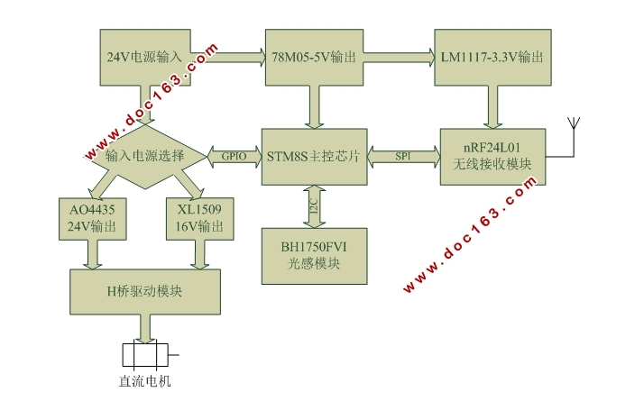
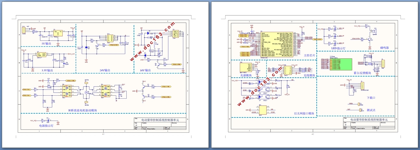
基于STM8S的智能电动窗帘控制器设计

1.无需注册登录,支付后按照提示操作即可获取该资料.
2.资料以网页介绍的为准,下载后不会有水印.资料仅供学习参考之用.
密 惠 保
基于STM8S的智能电动窗帘控制器设计(任务书,开题报告,外文翻译,论文16600字)
摘 要
二十一世纪信息化浪潮推动了计算机技术、通信技术、互联网技术的迅猛发展,智能家居、工业4.0等一些新概念为人们所熟知。智能电动窗帘的出现就是人与周围环境智能化互联的一个缩影。本文描述了智能电动窗帘控制系统的工作原理,给出了电动窗帘无线遥控模式和光控模式的具体解决方案。系统主要由控制器单元与遥控器单元两个部分组成。采用STM8S作为核心控制器,通过nRF24L01无线收发模块实现窗帘的半自动化远程控制,利用环境光强传感器BH1750FVI采集光照数据,根据光照强弱实现窗帘的自动化实时控制。使用H桥驱动电路控制直流电机实现窗帘的开合。系统设计引入了人性化元素,对于工业厂房大型窗帘、智能家居典型窗帘的自动化控制应用提供了依据,具有良好的市场前景。
关键词:STM8S nRF24L01无线模块 BH1750FVI环境光强传感器 H桥驱动电路
Intelligent Electric Curtain Control System Based on STM8S
Abstract
21st century wave of information technology promotes the rapid development of computer technology, communication technology and Internet technology. Some new concepts such as smart home, industrial 4.0 are well known. The emergence of intelligent electric curtain is a miniature of people and the surrounding environment interconnected. This paper describes the working principle of the intelligent electric curtain control system, providing specific solutions for wireless remote control model and photosensitive control model. System is mainly composed of two parts with controller unit and remote control unit. System utilizes STM8S as key controller through the wireless transceiver module nRF24L01 realize the half automation remote control of the curtain, using environmental luminous intensity sensor BH1750FVI collect illumination data, according to the illumination intensity to realize automatic real-time control of the curtain. Use H bridge driving circuit control DC motor to achieve the opening and closing of the curtain. Design introduces elements of human nature, provides a basis for large industrial plants curtains or typical smart home curtains automation control application, and with good market prospects.
[资料来源:www.THINK58.com]
Key Words: STM8S; nRF24L01; BH1750FVI; H bridge
[版权所有:http://think58.com]


目 录
摘 要 I
Abstract II
第一章 绪论 1
1.1 引言 1
1.2 研究背景和意义 1
1.3 研究现状 2
第二章 系统总体方案设计 3 [资料来源:http://think58.com]
2.1 系统模块组成 3
2.2 系统工作原理 4
第三章 系统硬件设计 5
3.1 主控芯片STM8S103K 5
3.2 电源模块设计 6
3.2.1 主控制器、光感模块5V供电 6
3.2.2 无线模块3.3V供电 7
3.2.3 H桥驱动模块24V和16V两档供电 8
3.3 H桥驱动模块设计 10
3.3.1 驱动原理 10
3.3.2 器件选型 11
3.3.3 工作时序 12
3.3.4 性能分析 13
3.4 无线射频收发模块设计 13
3.4.1 nRF24L01芯片描述 13
3.4.2 无线模块接口设计 14
3.5 光感模块设计 15
3.5.1 不同场合光照强度分析 15
3.5.2 BH1750FVI芯片描述 15
3.5.3 光感模块接口设计 16
3.6 处理器基本外围电路设计 16
3.6.1 复位电路 16
3.6.2 电源滤波与退耦电容电路 17
3.6.3 SWIM调试下载接口电路 17
3.6.4 蜂鸣器控制电路 18
第四章 系统软件设计 19
4.1 软件总体设计 19
4.1.1 软件设计概述 19
4.1.2 遥控器单元发射程序流程 19
4.1.3 控制器单元接收程序流程 20
4.2 功能模块程序设计 21
4.2.1 STM8S的GPIO口初始化 21
4.2.2 STM8S的SPI通信模块初始化 22
4.2.3 nRF24L01无线收发模块功能概述 22
4.2.4 nRF24L01增强型ShockBurstTM收发模式 23
4.2.5 STM8S的I2C通信模块初始化 26
4.2.6 BH1750FVI光感模块功能概述 26 [资料来源:www.THINK58.com]
4.2.7 BH1750FVI连续H分辨率测量模式 27
第五章 系统调试 30
5.1 STM8S的开发环境与开发工具 30
5.1.1 开发环境 30
5.1.2 开发工具 30
5.2 系统软硬件调试 31
5.2.1 系统硬件调试 31
5.2.2 系统软件调试 34
第六章 总结与展望 36
参考文献 38
致谢 39
附录一:系统总原理图 40
附录二:控制器单元PCB图 43
附录三:实物效果展示 43
