具有温度补偿的湿度测试模块的设计(附程序和原理图)

1.无需注册登录,支付后按照提示操作即可获取该资料.
2.资料以网页介绍的为准,下载后不会有水印.资料仅供学习参考之用.
密 惠 保
摘 要
本文介绍了以AVR为中央处理器的湿度测试模块的工作原理、硬件电路组成和软件设计等。该测试模块采用湿敏电阻及其它阻容元件构成振荡电路,将采集到的湿度样本信号转换成相应的频率信号,然后进行一定的温度补偿,再送至处理,最后显示其湿度值,是集温度补偿电路和LED显示于一体的湿度测试系统。其中,温度补偿电路选用的是DS18B20温度传感器作为测温元件,根据温度的变化对湿度测量值进行跟踪补偿,尽可能减少由温度引起的测量温漂和误差,以确保湿度测试的准确性。所以该测试模块具有测量精度高、智能性强、性能价格比优越等优点,可广泛应用于诸多领域的湿度测量。
关于本论文的研究工作,尤其是补偿温度误差方面的研究,将对今后的高精度湿度测量与控制具有实际意义。
本湿度测试模块具有精度高、测量范围宽、适应高湿环境等优点,并具有温度补偿,一定程度上减少了温漂和误差,提高了测量的准确性。
关键词:AVR单片机;湿度测试;温度补偿
The Design Of Humidity Test Module With Temperature Compensation
Abstract
This paper introduces the working principle of the humidity testing module who’s CPU is the AVR microcontroller, hardware and software design. The test module used humidity resistance and other components constitute a RC-oscillator circuit, the humidity will be collected samples signals into the corresponding frequency signal and then proceed to a certain temperature compensation, and then sent to the microcontroller, through its rapid processing, the final Showing the value of its humidity, temperature compensation circuitry is set and integrated LED display on the humidity testing system. The temperature compensation circuitry is selected as the temperature DS18B20 temperature sensor components, according to the change in temperature and humidity measurements to track compensation, as far as possible to reduce the temperature caused by temperature drift and the measurement error, to ensure the accuracy of testing humidity. Therefore, the test module with high accuracy, intelligent and strong, excellent price-performance advantages can be widely used in many fields and humidity measurements. [资料来源:http://www.THINK58.com]
On this thesis research, in particular compensation temperature error of research, will be the future high-precision measurement and control humidity of practical significance.
The humidity testing module has many advantages, such as high precision, range wide, high humidity environment, and has temperature compensation, to some extent, it has a decrease of temperature drift and error, and improves the accuracy of the measurements.
Key Words:MCU AVR;humidity measurement;temperature compensation
系统的总体设计
根据市场对湿度测试仪器的实际的要,本设计采用了单片机控制系统,主控芯片选用ATMEL公司的ATmega8单片机,解决了51系列单片机运行速度低,一般需扩展外部不掉电存储器的问题,为获得低的温度漂移,还进行了相应的温度补偿,实现了具有温度补偿的湿度测试模块的基本功能和相关信息的显示。
系统组成框图
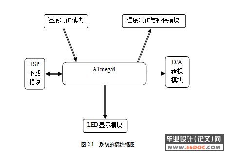
本设计主要分为湿度测试模块、温度测试与补偿模块、(D/A转换模块)、LED显示模块和ISP下载模块,具体结构如图2.1所示:
各模块的功能介绍
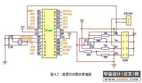
(1)湿度测试模块:它是该系统的入口,把湿度值以电信号的形式进行采集,送入到微处理器当中进行运算处理。
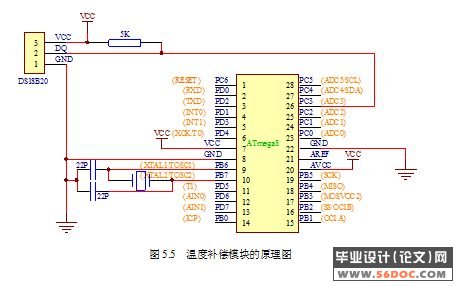
(2)温度测试与补偿模块:主要是为了满足在不同温度下的测量,扩大了该系统的测量范围,提高了测量精度,使得测量值更准确。
(3)湿度电压转换模块(D/A模块):该模块的作用是把测量到湿度转化为模拟量,作为该系统的输出。
(4)LED显示模块:该模块是显示所测量到的数字量,可以直观的看到该环境下的湿度值和温度值。
(5)ISP下载模块是用来给单片机写程序,并为以后该仪器的检测和重新修改程序提供了方便。 [资料来源:http://think58.com]
[资料来源:http://THINK58.com]
目 录 16000字
摘 要 I
Abstract II
引 言 1
1 概述 2
1.1 具有温度补偿的湿度测试模块的设计背景 2
1.1.1 国内外市场上的湿度测试模块的现状与发展趋势 2
1.1.2 目前具有温度补偿的湿度测试模块存在的问题 2
1.2 本文研究的主要内容 2
2 系统的总体设计 4
2.1 系统组成框图 4
2.2 各模块的功能介绍 4
3 主控芯片的选择 6
3.1 ATmega8单片机总体结构及引脚图 6
3.2 ATmega8的主要性能和特点 7
4 湿度测试模块的设计 8
4.1 湿度测量技术 8
4.2 选择湿度传感器注意的问题 8 [版权所有:http://think58.com]
4.3 CHR-01型湿敏电阻 9
4.3.1 CHR-01型湿敏电阻的外形尺寸及内部示意图 10
4.3.2 CHR-01型湿敏电阻的工作原理 10
4.3.3 CHR-01型湿敏电阻的性能参数 10
4.3.4 使用湿敏电阻注意的问题 11
4.4 LM358的介绍 11
4.4.1 LM358电路概述 11
4.4.2 LM358电路特性 11
4.5 湿度测试模块的功能及原理图 12
5 温度测试与补偿模块设计 13
5.1 温度补偿模块的研究 13
5.2 温度补偿模块的实现方案 13
5.3 DS18B20温度传感器 14
5.3.1 DS18B20的主要特征与优点 15
5.3.2 DS18B20的工作原理 16
5.3.3 DS18B20的工作时序介绍 17
5.4 温度补偿模块的组成原理图 18 [来源:http://think58.com]
6 电压转换模块(D/A)的设计 19
6.1 TLC5620 D/A转换器的功能特点 19
6.2 TLC5620 D/A的工作时序 20
6.3 TLC5620 D/A的原理图 21
7 LED显示模块的设计 22
7.1 74LS164芯片的介绍 22
7.2 LED数码管的介绍 22
7.3 LED显示的硬件连接 24
8 ISP下载模块的设计 25
9 软件设计 26
9.1 系统软件流程图 26
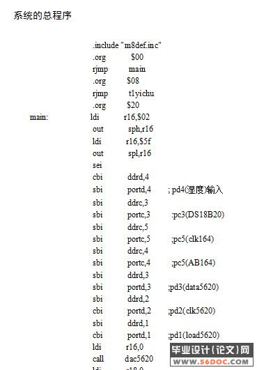
9.2 系统的总程序 26
结 论 36
参 考 文 献 37
附录A 系统硬件原理图 39
致 谢 40
[资料来源:http://THINK58.com]
[资料来源:http://www.THINK58.com]
