
旋转编码器控制阶跃电压研究
1.无需注册登录,支付后按照提示操作即可获取该资料.
2.资料以网页介绍的为准,下载后不会有水印.资料仅供学习参考之用.
密 惠 保
旋转编码器控制阶跃电压研究(论文10000字)
摘 要
阶跃电压是目前研究的热点方向,一个矩形的脉冲信号可以看作是由两个阶跃电压叠加而成,因此,阶跃电压被广泛地应用在各种电路的脉冲波形信号分析中,是一种非常重要的波形分析方法。采用阶跃电压的方法还实现了对交流电机电气参数的静态检测。然而,在工控系统中,阶跃电压使得电容在充放电过程中伴随着能量的损耗,可能造成器件的损坏。
在国家电力系统中,电网电压的波动现象经常发生,而这种现象在为井下作业供电的系统中表现的非常危险。为了保证井下工作人员的安全以及设备的安稳运行,矿井用的电压源必须满足检测要求,而现在常用的检测装置准确性偏低。为此本文介绍了一种以旋转编码器为控制端,以逻辑门、运算放大器等电子元器件为主电路实现电压阶跃的装置,对矿井电源电压的检测以及波形的分析具有十分重要的意义。
关键词:旋转编码器 阶跃电压 电子元器
ABSTRACT
Step voltage is a hot research direction at present. The pulse signal of a rectangle can be seen as a superposition of two step voltages. Therefore, step voltage is widely used in pulse waveform signal analysis of various circuits and is a very important waveform analysis method.The step voltage method is also used to realize the static detection of the electrical parameters of the ac motor.However, in the industrial control system, the step voltage makes the capacitor lose energy during charging and discharging, which may cause the device damage.
[资料来源:http://THINK58.com]
In the national power system, fluctuations in grid voltage occur frequently, which can be very dangerous in systems that provide power for underground operations.In order to ensure the safety of underground workers and the safe operation of equipment, the voltage source used in the mine must meet the detection requirements, but the accuracy of the commonly used detection devices is low.For this reason, this paper introduces a kind of device that USES the rotary encoder as the control end, logic gate, operational amplifier and other electronic components as the main circuit to realize voltage step, which is of great significance to the detection of mine power supply voltage and the analysis of waveform.
KEYWORDS: Rotary encoder, Step voltage, Electronic components
[资料来源:www.THINK58.com]
目 录
第一章 绪论 1
1.1. 课题研究的背景和意义 1
1.2. 课题研究的主要内容 1
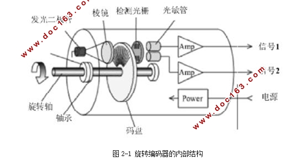
1.3. 旋转编码器简介 2
第二章 旋转编码器的相关信息 3
2.1. 旋转编码器的分类 3
2.2. 旋转编码器的结构及工作原理 3
第三章 电路的设计思路,相关元器件的选材 6
3.1. 电路设计思路 6
3.2. 电子元器件选材与误差分析 8
3.3. CD4011与非门 9
3.3.1. CD4011引脚图 9
3.3.2. CD4011真值表 9
3.3.3. 工作原理 10
3.4. CD4053模拟开关 10
3.4.1. CD4053引脚图 11 [资料来源:http://think58.com]
3.4.2. CD4053引脚功能表 11
3.4.3. CD4053真值表 12
3.5. CA3140运算放大器 13
3.5.1. CA3140引脚图 13
3.5.2. CA3140引脚功能表 13
第四章 实验具体操作步骤,实验数据 15
4.1. 旋转编码器接线 15
4.2. CD4011与非门接线及各脚输出信号分析 16
4.3. CD4053模拟开关接线及开关闭合情况分析 16
4.4. CA3140运算放大器接线及输出波形分析 16
4.5. OUTPUT端输出波形随编码器旋转变化情况分析 17
4.6. 波形记录与分析 18
4.7. 电路板焊接 19
第五章 输出电压阶跃幅度与理论计算结果对比、结论 21
致谢 24 [资料来源:THINK58.com]