五菱微型汽车悬架系统设计(含CAD零件图装配图)

1.无需注册登录,支付后按照提示操作即可获取该资料.
2.资料以网页介绍的为准,下载后不会有水印.资料仅供学习参考之用.
密 惠 保
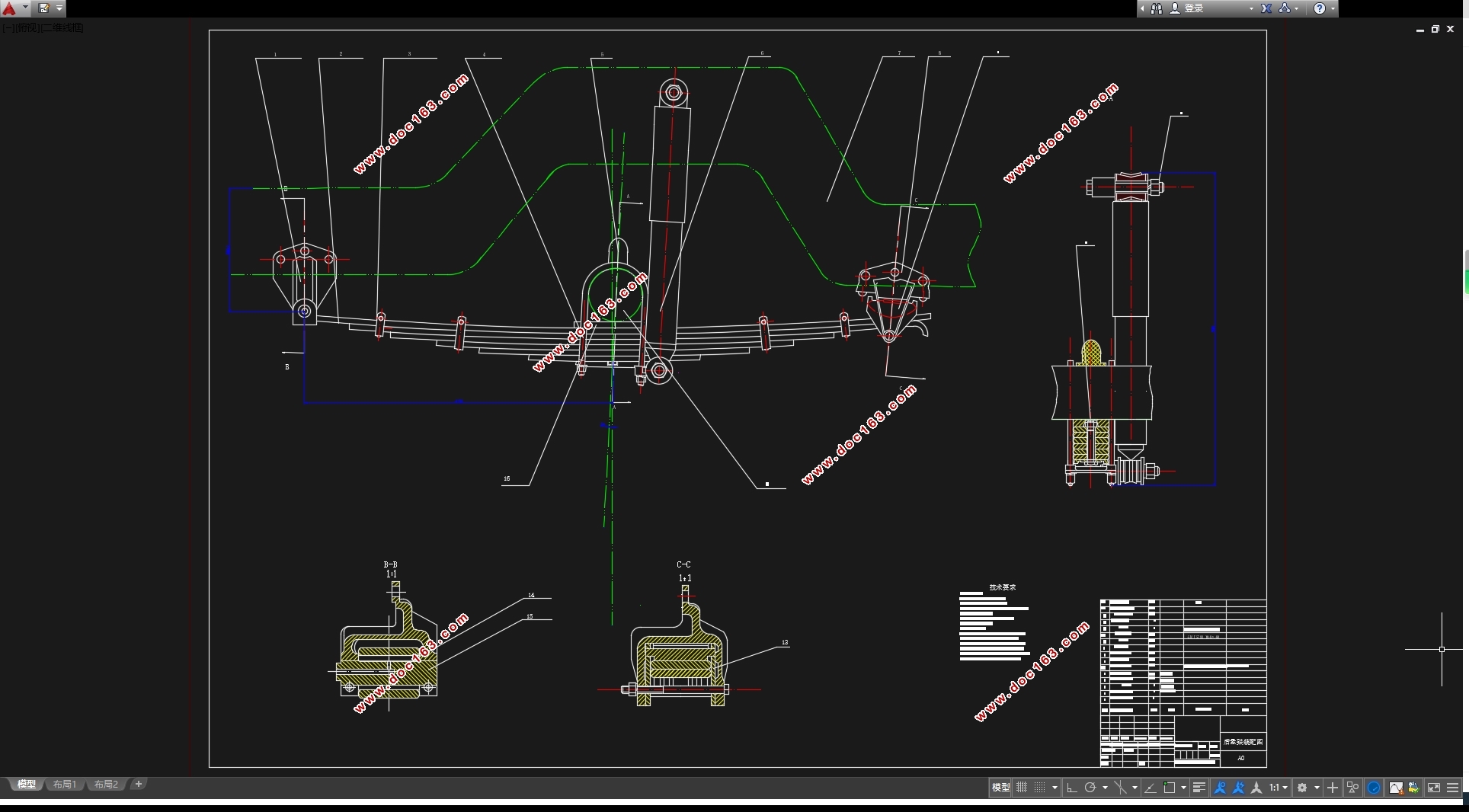
五菱微型汽车悬架系统设计(含CAD零件图装配图)(任务书,开题报告,外文翻译,论文说明书13200字,CAD图纸5张)
摘 要
悬架是汽车底盘上的重要组成部分,能影响车辆性能中的操纵平稳性和行驶顺利性。
本文通过对已有的微型车结构进行分析,并在参考了五菱微型车结构的情况下,对微型车的前后悬架系统进行了设计,并对该设计进行了校核,并用 CAD软件对设计的悬架进行了绘制。在该设计中重点考虑悬架会影响的行驶平顺性和操作舒适性,并结合了经济性,前面选择麦弗逊悬架,而后面就选择钢板弹簧。麦弗逊悬架的结构不复杂,体积较小,易于操作而且很稳定,在生产中有许多应用。而钢板弹簧它不需要设计导向机构,而且易于制造,经济成本低,多应用于微型车后悬架。本论文综合应用了汽车设计、汽车理论、汽车工程手册、机械设计手册等等基本原理,并在已有的悬架设计的理论基础上设计计算了微型车的悬架系统,经过验证分析,得出了设计结果,对现代汽车悬架系统的设计有一定的现实意义,同时也得到优化的悬架,对以后的汽车设计有了很大的帮助。
关键词:悬架系统;麦弗逊悬架;钢板弹簧;微型车;设计
Abstract
Suspension is an important part of automobile chassis,it has great influence on the steering stability and riding comfort of vehicle performance. [资料来源:http://THINK58.com]
This paper analyzed the structure of existing minivans. In the case of reference the WULING structure, I design the front and rear suspensions of the minivans. And check the design and use the CAD software to draw the structure of the suspension. The key consideration of the suspension is the riding comfort and manipulation of comfort. With combining the economy, I choose the Macpherson suspension as the front suspension and choose the leaf spring as the rear suspension. Macpherson suspension structure is simple, it takes up less
space, has a good manipulation of good stability and wide application. And when considering the leaf spring, I don’t need to design steering mechanism, and it’s easy to manufacture and its economic cost is low. It is more applied in the rear suspension. This paper integrated the application of the automobile design, automobile theory, automobile engineering manual, and so on. Based on the existing suspension design and the theory of design, I have the calculation of the mini vehicles suspension system. Having validated the analysis, the design is obtained as the result. The design of modern automobile suspension system has certain practical significance. In the same time ,I get the optimized suspension with great help for the future vehicle design.
[来源:http://www.think58.com]
Key Words: Suspension system; Macpherson suspension; leaf spring; mini vehicle; design
2.3给定参数
1)长×宽×高:3810mm×1510mm×1820mm
2)轴距:2500mm;轮距(前/后):1290mm/1290mm
3)最小离地间隙:160mm
4)汽车总质量:1575kg;整车整备质量:975kg;
5)空载轴荷分布: 前轴 540kg 后轴 435kg
6)满载负荷分布: 前轴 715kg 后轴 860kg
7)最高车速:110km/h
8)最大功率:45kw/5600rpm;最大扭矩:85N.m/3500~4000rpm
9)轮胎规格: 165/70 R13
[资料来源:http://think58.com]


目录
摘 要 I [资料来源:http://www.THINK58.com]
Abstract II
第1章 绪论 1
1.1 引言 1
第2章 悬架结构形式分析和选择,设计要求及给定参数 3
2.1悬架结构形式分析和选择 3
2.1.1悬架的结构分类 3
2.1.2悬架的优缺点 3
2.1.3悬架设计的选择 4
2.2悬架的设计要求 4
2.3给定参数 5
第3章 悬架系统主要参数的计算 6
3.1 悬架静挠度 的计算 6
3.2 悬架的动挠度 6
3.3 悬架弹性特性 6
3.4 悬架簧上质量 8
3.5后悬架中主簧和副簧之间刚度的分配 8
3.6悬架侧倾角刚度及在前、后轴的分配 8
第4章 弹性元件的设计计算 10
4.1钢板弹簧的布置方案 10
4.2钢板弹簧的主要参数的确定 10
4.2.1满载弧高 的确定 10 [来源:http://think58.com]
4.2.2 钢板弹簧长度的确定 11
4.2.3钢板断面尺寸及片数的确定 11
4.2.4钢板弹簧各片长度的确定 13
4.2.5 钢板弹簧的刚度验算 14
4.2.6 钢板弹簧总成在自由状态下的弧高及曲率半径计算 15
4.2.7钢板弹簧总成弧高的核算 16
4.2.8钢板弹簧的强度验算 16
第5章 麦弗逊悬架弹性元件的设计计算及校核 19
5.1 弹性元件的设计和计算 19
5.1.1弹簧形式和材料的选择 19
5.1.2 弹簧刚度的计算 19
5.1.3 螺旋弹簧的最大冲击力的计算 19
5.1.4 螺旋弹簧的材料的许用应力 20
5.1.5 按满载计算弹簧钢丝直径d 20
5.1.6 弹簧完全并紧时的高度 和自由高度 21
5.2 弹簧的校核 21
5.2.2 弹簧表面切应力的校核 21
5.2.3平顺性的校核 22
第6章 减震器和横向稳定杆及导向机构的设计计算 23 [资料来源:http://THINK58.com]
6.1 减震器的类型和其参数的设计计算 23
6.1.1减震器的分类 23
6.1.2双筒式液力减震器的工作原理 24
6.1.3 相对阻尼系数 的计算 24
6.1.4减震器阻尼系数 24
6.1.5 减震器最大卸荷力 的确定 25
6.1.6 减震器工作缸直径D的确定 25
6.2 横向稳定杆的设计 26
6.2.1 横向稳定杆的作用 26
6.2.2 横向稳定杆参数的确定 26
6.2.3 横向稳定杆的刚度校核 28
6.3 独立悬架导向机构的设计 28
6.3.1 导向机构设计要求 28
6.3.2 麦弗逊式独立悬架的侧倾中心 29
第7章 结论 31
参考文献 32
致谢 33 [资料来源:http://think58.com]
上一篇:电动工程车电池包虚拟设计(含CAD零件装配图,CATIA三维图)
下一篇:多轴汽车电液辅助转向系统设计(含CAD零件图装配图,CATIA三维图)
