SUV后驱动桥的设计(含CAD零件图装配图)

1.无需注册登录,支付后按照提示操作即可获取该资料.
2.资料以网页介绍的为准,下载后不会有水印.资料仅供学习参考之用.
密 惠 保
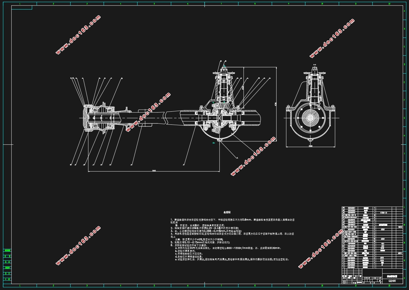
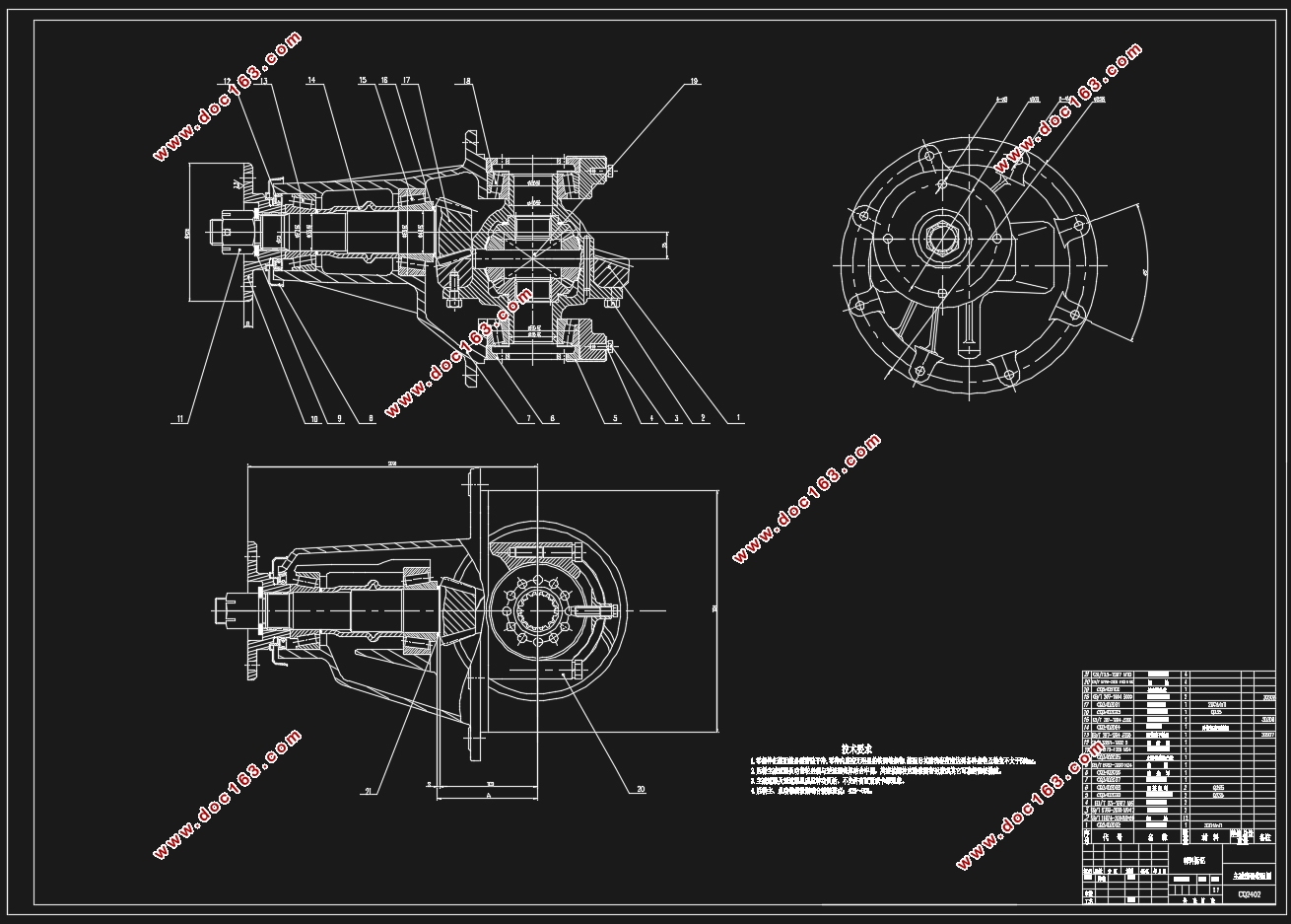
SUV后驱动桥的设计(含CAD零件图装配图)(任务书,开题报告,外文翻译,文献摘要,论文说明书11600字,CAD图纸7张)
摘 要
后桥是汽车各种组合部件中非常重要的一环,它的能力将会对SUV的使用性能产生积极或消极的作用。后桥的主要作用是加大由汽车变速器和传动轴传导过来的转矩,并将一同传来的转速降低后传给其所连接的车轮,同时汽车整体所遭受的各个方向的力也将由后桥来承担。通过设计一个经济适用的后桥,可以大大提升汽车动力性行驶性等各项性能。
本次对后桥的设计计算有以下几项:主减速器的设计计算、差速器的设计计算、半轴的设计计算和驱动桥壳受力分析。主减速器的形式选择为单级主减速器;差速器形式选择普通圆锥齿轮差速器;传动装置选择全浮式半轴;桥壳则选用整体式桥壳。计算完毕后,将会使用AutoCAD 和SolidWorks等绘图软件绘制出SUV后桥的总装配图和部分零件图,以便于制作。
关键词:后桥;主减速器;差速器;半轴;桥壳
Abstract
Rear axle is one of the most important assembiles of the automobile. Its performance directly influences the performance of SUV. The basic functions of the rear axle is to increase the torque which comes from the drive shaft and transmission, also reduce the rotation speed and transfer them to the left and right wheels. Rear axle also can bear the vertical force, lengthways force and transversals force which come from the ground, carframe and the body of car. With designing a suitable and affordable rear axle, the power performance, trafficability characteristic and safety of the SUV can be improved greatly.
[来源:http://think58.com]
In this report, the design of rear axle contains the design of main reducer, differential mechanism, transmitted apparatus and the housing of driving axle. The main reducer we will use single reduction gear, the differential mechanism will use common taper planet gear. The transmission apparatus will adopt full floating axle shaft and the housing of driving axle will use the whole pattern. After the calculating, we will use AutoCAD, Solidworks and other softwares to draw the assembly drawing and some part drawing of the SUV rear axle, in order to manufacture easily.
Key Words:Rear axle; main reducer; differential mechanism; half shaft; housing
主减速比的确定
通过设计任务书可以得到主减速比i_0=4.625。确定最大传动比时,需要考虑汽车最低档时最大爬坡度能否满足要求,最高档时最高车速能否满足要求。所以在此需要验证此主减速比能否满足汽车最大爬坡度和最高车速的要求。


目录
摘 要 II
Abstract I
第1章 绪论 1 [来源:http://www.think58.com]
1.1 SUV后桥简介 1
1.2 国内外SUV后桥研究状况 1
1.3 SUV后桥设计的要求 1
第2章 后桥的结构形式及选择 3
2.1 后桥结构形式 3
2.2 主减速器的结构形式 3
2.3 差速器的结构形式 5
2.4 传动装置的结构形式 5
2.5 桥壳的结构形式 5
第3章 后桥设计计算 7
3.1 主减速器设计计算 7
3.1.1 主减速比的确定 7
3.1.2 主减速器齿轮载荷计算 8
3.1.3 主减速器齿轮基本参数选择 10
3.1.4 主减速器锥齿轮的材料 11
3.1.5 主减速器锥齿轮尺寸计算 12
3.1.6 主减速器齿轮的强度计算 14
3.2 差速器的计算 17
3.2.1 差速器齿轮主要参数选择 17
3.2.2 差速器齿轮的材料 19
3.2.3 差速器齿轮几何尺寸计算 19 [版权所有:http://think58.com]
3.2.4 差速器齿轮强度计算 22
3.3 全浮式半轴的设计 23
3.3.1 半轴基本参数计算及校核 23
3.3.2 半轴花键设计、材料选取及热处理方法 24
3.4 驱动桥壳设计 25
3.4.1 桥壳的结构形式 25
3.4.2 桥壳的受力与强度校核 25
3.5 总结与展望 26
参考文献 28
致谢 29
[资料来源:THINK58.com]
上一篇:轻型电动物流车动力系统设计(含CAD图,CATIA三维图)
下一篇:中型货车双级传动的后驱动桥设计(含CAD零件图装配图)
